Network communication system, data transmission method and readable storage medium

A data transmission method and network communication technology, applied in the field of network communication systems, data transmission methods and readable storage media, can solve problems such as affecting user network communication experience, and achieve the effect of improving network communication experience and maintaining production costs

Pending Publication Date: 2022-04-01
成都康特软件科技开发有限公司
0 Cites 0 Cited by

AI-Extracted Technical Summary

Problems solved by technology

[0003] However, it is worth noting that most of the network devices currently on the market are general-purpose devices that can be mass-produced and designed by manufacturers out of production cost considerations. Such general-purpose devices need to be configured with the same IP ...

Method used

In summary, in the network communication system, the data transmission method and the readable storage medium provided by the embodiment of the application, the network communication system provided by the application connects the user terminal and the first communication port of the switch to each other, and connect multiple network devices to a second communication port of the switch, and then create multiple virtual network cards at the user terminal to ensure that each network device corresponds to a virtual network card and is in the same v...

Abstract

The invention provides a network communication system, a data transmission method and a readable storage medium, and relates to the technical field of network communication. According to the network communication system provided by the invention, the user terminal is mutually connected with the first communication port of the switch, the plurality of network devices are respectively connected with the second communication port of the switch, and then the plurality of virtual network cards are simulated and created at the user terminal; and each network device independently corresponds to one virtual network card and is located in the same virtual local area network with the virtual network card, so that the network communication system substantially establishes a plurality of virtual local area networks which simultaneously comprise the user terminal and do not interfere with each other, thereby ensuring that the user can access the virtual local area network without modifying the factory IP address of each network device. Data interaction is directly carried out through the user terminal and a plurality of network devices, so that the network communication experience of a user is improved, and the production cost of the network devices is effectively maintained.

Application Domain

Networks interconnection

Technology Topic

Data transmissionIp address +7

Image

  • Network communication system, data transmission method and readable storage medium
  • Network communication system, data transmission method and readable storage medium
  • Network communication system, data transmission method and readable storage medium

Examples

  • Experimental program(1)

Example Embodiment

[0044] In order to make the objects, technical solutions, and advantages of the present application, the technical solutions in the present application embodiment will be described in connext of the present application embodiment, and It is a part of the present application, not all of the embodiments. Components of the present application embodiments described and illustrated in the drawings herein can be arranged and designed in a variety of different configurations.
[0045]Thus, the following detailed description of the embodiments of the present application provided in the drawings is not intended to limit the scope of the present application claimed, but only the selected embodiments of the present application. Based on the embodiments in the present application, all other embodiments obtained without creative labor are not made in the pre-creative labor premises.
[0046] It should be noted that similar reference numerals and letters represent the similar items in the following figures, and therefore, once one is defined in one bysertation, it is not necessary to further define and explain it in the following drawings.
[0047] In the description of the present application, it is to be understood that the term "first" and "second" and the like are used only to separate an entity or operation with another entity or operating area, not necessarily required. Or implies any such actual relationship or order between these entities or operations. Moreover, the term "comprising", "comprising" or any other variable is intended to cover non-exclusive contained, thereby enabling a process, method, article, or device including a series of elements, not only those elements, but also not expressly listed. Other elements, or elements that are also inherent to such processes, methods, items, or equipment. In the absence of more restrictions, the elements defined by the statement "include a ...", and there is no additional same elements in the process, method, item, or apparatus including the element. The specific meaning of the above terms in the present application can be understood in terms of one of ordinary skill in the art.
[0048] Some embodiments of the present application will be described in detail below with reference to the accompanying drawings. In the case of an unable conflict, the following embodiments and features in the embodiments can be bonded to each other.
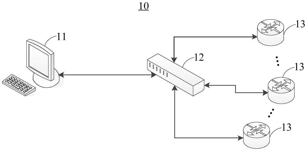
[0049] Please refer to figure 1 , figure 1 It is a schematic diagram of the network communication system 10 provided by the embodiment of the present application. In the present application embodiment, the network communication system 10 can enable the user to interact between the user terminal 11 and multiple network devices 13 without modifying the factory IP address of the network device 13, thereby maintaining the current While producing the production cost of network device 13, it is necessary to avoid the user's network communication experience for the network device 13 to perform IP address adjustment operations for network devices 13. The factory IP address is used to indicate the IP address that the corresponding network device 13 has been maintained from the factory; the user terminal 11 can be, but not limited to, smartphones, personal computers, tablets, laptops, etc.
[0050] In the present application embodiment, the network communication system 10 can include a user terminal 11, a switch 12, and a plurality of network devices 13 having the same factory IP address. The user terminal 11 is connected to each other with a first communication port of the switch 12, and a plurality of the network device 13 each connects a second communication port of the switch 12. Among them, the user terminal 11 simulates a plurality of virtual network cards, where the total number of virtual network cards is the same, each of the total number of network devices, each of which corresponds to a virtual network card, and is in the same virtual local area network with the virtual network card. The different network devices 13 respectively correspond to a virtual local area network, whereby each virtual local area network corresponds to a second communication port of the switch 12 and a virtual network card of the user terminal 11.
[0051] In this case, the network communication system 10 is essentially equivalent to a plurality of virtual local area networks that are inconsistent with each other of the user terminal 11, even if the factory IP address of the network device 13 in each virtual local area is the same. It is also possible to directly transmit data transmission to the network device 13 that needs to be accessed directly by defining a virtual local domain network that needs to be transmitted and the second communication port corresponding to the virtual local area network, thereby ensuring that the user can do not modify each network device 13. In the case of a factory IP address, data interaction directly through the user terminal 11 with multiple network devices 13, to enhance the user's network communication experience, and effectively maintain the production cost of network equipment.
[0052] In the present application embodiment, the virtual IP addresses of the plurality of the virtual network cards are different, and they have the same IP network segment as the factory IP address to ensure that each of the virtual network cards can be in a virtual local area network. The network device 13 performs data interaction.
[0053] The switch 12 has 47 second communication ports, and 47 network devices 13 having the same factory IP address "192.168.10.253" are described as an example, where each network device 13 is connected to one of the second communication ports of the switch 12. And the virtual local area to which each two communication port is given, "VLAN2", "VLAN3", ..., "VLAN 47", "VLAN48" to characterize the identity of the virtual local area network through each virtual LAN ID. At this time, the corresponding simulation creates 47 virtual network cards at the user terminal connected to the first communication port of the switch 12, so that each virtual network card corresponds to a virtual local area network identity, and makes the 47 virtual network cards respectively virtual IP address. It can be expressed in turn to "192.168.3", "192.168.10.47", "192.168.10.47", "192.168.10.48", and in turn, the aforementioned virtual local area network identifies "VLA2", "VLAN3", ..., " VLAN47 "," VLAN48 ". In this case, these 47 virtual network cards will have the same IP network segment "192.168.10" as the factory IP address "192.168.10.253".
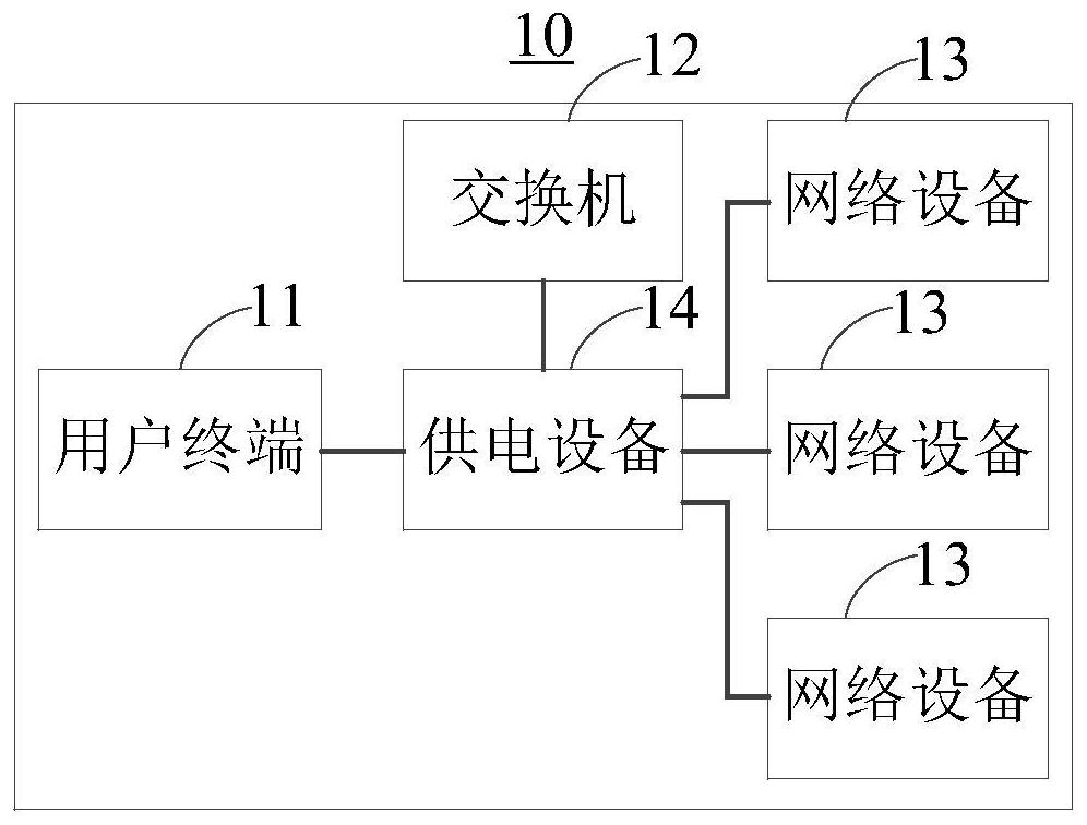
[0054] Optionally, please refer to figure 2 , figure 2 It is a schematic diagram of the composition of the network communication system 10 provided in the present application embodiment. In the present application embodiment, the network communication system 10 also includes a power supply device 14, which is electrically connected to the user terminal 11, the switch 12, and each of the network devices 13 for The user terminal 11, the switch 12, and each of the network device 13 provide electrical energy. In one embodiment of the present embodiment, the power supply device 14 may be obtained by a plurality of power supply units, each of which corresponds to an electronic device (eg, the user terminal 11 or the switch 12). Transaction.
[0055] In the present application, in order to ensure that the user can smoothly perform data interaction with the plurality of network device 13 through the user terminal 11, the present application implements the above functions by providing a data transmission method applied to the network communication system 10. The data transmission method provided herein will be described below.
[0056] Please refer to image 3 , image 3 One of the flow schematic of the first data transmission method provided by the embodiment of the present application. In the present application embodiment, the first data transmission method can include steps S210 and step S220.
[0057] Step S210, the user terminal adds the respective virtual network card to the same TRUNK, and transmits a plurality of to-be transmitted packets to the switch by the first communication port of the switch.
[0058] In the present embodiment, the user terminal 11 can generate a message to be transferred to different network devices 13 in response to a user operation, and the user terminal 11 will be transmitted separately by each of its virtual network cards. Ways, determine if data interaction is performed. Among them, if there is a virtual network card to be transferred, the source IP address of the message to be transferred is the virtual IP address of the virtual network card to be transferred, and the destination IP address of the message to be transferred. For the factory IP address, the pending message will correspond to the virtual local area network identity corresponding to the virtual network card to be transferred to the message to be transmitted, so that the switch 12 determines which second communication needs to be transmitted. Port is transmitted.
[0059] A virtual network card 1 corresponding to the virtual local area network identifies "VLAN2", when the virtual network card 1 generates a message to be transferred, the source IP address of the message to be transferred is virtual IP address of the virtual network card 1 "192.168 .10.2 ", the destination IP address to be transmitted is the factory IP address" 192.168.10.253 ", which logs that the virtual local area network recorded by the message is identified as the virtual local area network identifier" VLAN2 "corresponding to the virtual network card 1.
[0060] When the user terminal 11 determines that the respective virtual network cards are generated, the generated plurality of the pending packets will be added to the same trunk to pass through the switch connected to the user terminal 11. 12 The first communication port of 12 is transmitted to the switch 12 to the switter 12.
[0061] Step S220, the switch reads the virtual local area network identity included in the transmitted message for each of the received packets, and selects the second communication port corresponding to the virtual local area network to transmit the information to be transmitted. Network devices connected to the second communication port.
[0062] In the present embodiment, since the multiple network device 13 has the same factory IP address, the destination IP address of all the transmitted packets received by the switch 12 is the factory IP address, so the switch 12 is determined. When each said network device 13 needs to be transferred to which network device 13 is forwarded, it is necessary to distinguish the network device to be transferred to the network device to be transmitted by reading the virtual local area network identity included in each of the pending messages. 13. Among them, after each of the information to be transferred, the switch 12 selects the second communication port corresponding to the virtual LAN ID to be transmitted to the second communication port corresponding to the virtual local area network identification. The text is transmitted to transmit the information to be transferred to the network device 13 that needs to be transmitted.
[0063] Thus, the present application can pass through steps S210 and step S220, the user can access multiple network devices 13 simultaneously accessed by the user terminal 11 without modifying the factory IP address of each network device 13.
[0064] Optionally, please refer to Figure 4 , Figure 4 It is a flow schematic diagram of the first data transmission method provided by the embodiment of the present application. In the present application embodiment, the first data transmission method may further include steps S230 and step S240.
[0065] Step S230, each network device transmits the target data packet to the switch by the second communication port connected to the network device.
[0066] In the present embodiment, after each network device 13 receives a message to be transferred from the user terminal 11, the corresponding source IP address can be extracted from the pending message to determine 13 of the network device 13. The virtual network card of the same virtual local area network, at which point the source IP address is a virtual IP address of the virtual network card in the same virtual local area network with the network device 13. Therefore, when a network device 13 generates a target data message that needs to be transmitted to the user terminal 11, the destination IP address of the target data message is in the same virtual local area network with the network device 13 generated by the target data. The virtual IP address of the virtual network card, the source IP address of the target data message, is the factory IP address of the network device 13 of the target data message, which will record the network that generates the target data message. Virtual LAN ID corresponding to device 13.
[0067] After the network device 13 generates a target data packet, the generated target data packet is transmitted to the switch 12 through the second communication port of the switch 12 to the network device 13.
[0068] Step S240, the switch transmits the target data packet to the user terminal to the user terminal with the target data packet to the user terminal to the user terminal to the user terminal.
[0069]In the present embodiment, when the switch 12 receives a target data message, the virtual local area network identity included in the target data message is read accordingly to determine if the target data message needs to be transmitted to other networks. Device 13, whether it is necessary to transmit to the user terminal 11. Among them, when the virtual LAN ID recorded by the target data message is matched to each other with the virtual local area where the network device generated by the target data packet is matched, that is, the target data packet needs to be transmitted to the user terminal 11, and is not transmitted. To other network devices 13. At this time, the switch 12 transmits the target data packet to the user terminal 11 by a first communication port connected to the user terminal 11, so that the user terminal 11 assigns the target data message to the corresponding. The virtual IP address is the same virtual network card as the source IP address of the target data packet. At this time, the virtual network card that receives the target data message is identified by the same virtual LAN ID.
[0070] Thus, the present application can implement data feedback of each network device 13 and the user terminal 11 by performing the above-described steps S230 and step S240.
[0071] In the present application, in order to ensure data interaction with the user terminal 11 in the network communication system 10, the network device 13 having the same factory IP address, the present application provides a user terminal applied to the network communication system 10. The data transfer method implements the above functions. The data transmission method provided herein will be described below.
[0072] Please refer to Figure 5 , Figure 5 It is a flowchart of the second data transmission method provided by the embodiment of the present application. In the present application embodiment, the second data transmission method may include steps S310 and step S320.
[0073] Step S310, detects whether or not there is a transmission message at each virtual network card.
[0074] In this embodiment, the source IP address of the source IP address to be transferred at each virtual network card is the virtual IP address of the virtual network card, the destination IP address of the to be transmitted, is a factory IP address, the pending The packet records the virtual local area network identity corresponding to the virtual network card where the message to be transferred.
[0075] Step S320, add different virtual network cards to the same trunk, and send multiple peers to be transferred to the switch by the first communication port of the switch, by the switch through the virtual local area network in the message to be transferred. The corresponding second communication port will be transferred to the corresponding network device to be transmitted.
[0076] Thus, the present application can achieve the effect of the user terminal 11 simultaneously accesses the effect of the user terminal 11 simultaneously accessed by performing the above-described steps S310 and Step S320.
[0077] Optionally, please refer to Image 6 , Image 6 It is a second schematic diagram of the second data transmission method provided by the embodiment of the present application. In the present application embodiment, the second data transmission method may further include steps S330 and step S340.
[0078] Step S330, the receiving switch is transmitted through the first communication port.
[0079] In the present embodiment, the target data packet is generated by a network device 13 connected to the switch 12, the source IP address of the target data message, is the factory IP address, the target dataset The purpose IP address of the text is a virtual IP address of the virtual network card from the same virtual local area network from the network device 13 from the target data message, the target data packet records corresponding to the network device 13 from which the target data message is obtained. Virtual LAN ID.
[0080] Step S340, assign the target data packet to the virtual network card corresponding to the virtual LAN in accordance with the virtual local area network identity included in the target data packet.
[0081] Thus, the present application can receive data feedback from each network device 13 to the user terminal 11 by performing the above-described steps S330 and Step S340.
[0082] In the present application, in order to ensure that the switch 12 in the network communication system 10 can be adjusted to data interaction between the user terminal 11 and the network device 13 having the same factory IP address, the present application is provided to the above network communication system. The data transmission method of the switch 12 in 10 implements the above functions. The data transmission method provided herein will be described below.
[0083] Please refer to Figure 7 , Figure 7 It is one of the flow schematic of the third data transmission method provided by the embodiment of the present application. In the present application embodiment, the third data transmission method includes steps S410 and step S420.
[0084] Step S410, the receiving user terminal is transmitted through the first communication port.
[0085] In the present embodiment, the source IP address from the user terminal 11 to be transferred to the user terminal 11 is a virtual IP address of the virtual network card to be transmitted to the message to be transmitted, the pending message. The destination IP address is the factory IP address, the pending message records the virtual LAN ID corresponding to the virtual network card where the message to be transferred is recorded.
[0086] Step S420, read the virtual local area network identity included in the message to be transferred for each, and select the second communication port corresponding to the virtual LAN ID to transmit the information to the second communication. The network device connected to the port.
[0087] Thus, the present application can implement the switch 12 to adjust the user terminal 11 simultaneously by performing the above-described steps S410 and S420.
[0088] Optionally, please refer to Figure 8 , Figure 8 It is a flow schematic diagram of the third data transmission method provided by the embodiment of the present application. In the present application embodiment, the third data transmission method may further include steps S430 and step S440.
[0089] Step S430 receives a target data message transmitted by multiple network devices through the second communication port.
[0090] In the present embodiment, the destination IP address of each of the target data packets is a virtual IP address of the virtual network card from the same virtual local area network from the network device 13 from the target data message, each of the target data packets. The virtual LAN ID corresponding to the network device 13 from the target data message is recorded, and the source IP address of each of the target data packets is the factory IP address.
[0091] Step S440, for each target data packet, transmit the target data packet to the user terminal with the same virtual local area network identifier with the target data packet through the first communication port.
[0092] Thus, the present application can implement the switch 12 to adjust the switch 12 to the user terminal 11 to perform data feedback to the user terminal 11 by performing the above-described steps S430 and S440.
[0093] In the embodiments provided herein, it should be understood that the disclosed devices and methods can also be implemented in other ways. The device embodiment described above is merely a schematic, for example, flowcharts and block diagrams in the drawings, showing the possible implementation of the device, method, and computer program product according to the embodiment of the present application. Function, and operation. In this regard, each of the flowcharts or block diagrams can represent a portion of a module, block, or code, a portion of the module, block, or code contains one or more of the blocks for implementing a predetermined logic function. Executive instructions. It should also be noted that in some implementations of the replacement, the functions labeled in the box can occur in a different order than those labeled in the drawings. For example, two consecutive blocks can actually be performed in parallel, and they can sometimes be performed in reverse order, which is determined according to the functions involved. It is also to be noted that each block in block diagram and / or flowchart, and a combination of block diagrams and / or box in block diagram, can be implemented with dedicated hardware-based systems that perform specified functions or motions. Or can be implemented with a combination of dedicated hardware to computer instructions.
[0094] In addition, each functional module in the various embodiments of the present application can be integrated together to form a separate portion, or each module is alone, or two or more modules can be integrated into a separate portion.
[0095] The function can be stored in one readable storage medium if the software function module is implemented as a separate product sales or in use. Based on this understanding, the technical solution of the present application essentially ors the portion of the prior art or part of the technical solution can be embodied in the form of software products, the computer software product is stored in a readable storage medium. While including a number of instructions to make a computer device (can be a personal computer, server, or network device, etc.) to perform all or some steps of the methods described in the various embodiments of the present application. The aforementioned readable storage medium includes: U disk, mobile hard disk, read-only memory (ROM, RAD-ONLY MEMORY), random access memory (RAM, RANDOM Access Memory), disk or optical discs can store program code Medium.
[0096] In summary, in the network communication system, data transmission method, and readable storage medium provided in the present application embodiment, the network communication system provided herein is connected to each other by causing the user terminal to each other with the first communication port of the switch, and makes more A network device is connected to a second communication port of the switch, followed by simulating a plurality of virtual network cards at the user terminal, ensuring that each network device corresponds to a virtual network card and is in the same virtual LAN in the same virtannet with the virtual network card to make network communication The system substance has a plurality of virtual local area networks that include mutual interference including the user terminal to ensure that the user can directly pass the user terminal directly with multiple network devices without modifying the factory IP address of each network device. To enhance the user's network communication experience and effectively maintain the production cost of network equipment.
[0097] As described above, only the various embodiments of the present application, but the scope of the present application is not limited thereto, and any technicress, those skilled in the art, can easily think of change or replacement within the technical scope of the present application, It should be covered within the scope of protection of this application. Therefore, the scope of protection of the present application shall be based on the scope of protection of the claims.

PUM

no PUM

Description & Claims & Application Information

We can also present the details of the Description, Claims and Application information to help users get a comprehensive understanding of the technical details of the patent, such as background art, summary of invention, brief description of drawings, description of embodiments, and other original content. On the other hand, users can also determine the specific scope of protection of the technology through the list of claims; as well as understand the changes in the life cycle of the technology with the presentation of the patent timeline. Login to view more.
Why Eureka
Try Eureka