Ceramic tile knocking equipment for building

A technology for building and ceramic tiles, applied in the direction of construction and building structure, can solve the problems of uneven force, broken tiles, etc., and achieve the effect of avoiding the residual agglomeration of concrete

Active Publication Date: 2022-04-05
陕西铜川煤矿建设有限公司
View PDF8 Cites 0 Cited by
  • Summary
  • Abstract
  • Description
  • Claims
  • Application Information

AI Technical Summary

Problems solved by technology

[0005] In order to overcome the above-mentioned patent, although the ceramic tiles can be knocked firmly, when encountering the tilted ceramic tiles, the direct knocking is easy to cause uneven force and cause the tiles to be broken. It can also press the lifted tiles tightly, without affecting the compaction equipment for building tiles.

Method used


Image

  • Ceramic tile knocking equipment for building
  • Ceramic tile knocking equipment for building
  • Ceramic tile knocking equipment for building

Examples


Embodiment 1

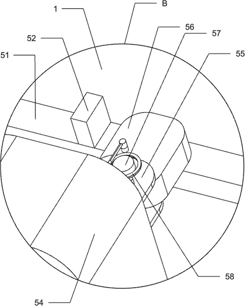
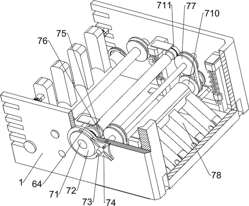
[0037] A building tile knocking in the equipment, including housing 1, roller 2, rotating shaft 21, rubber wheel 3, drive mechanism 4, and knocking mechanism 5, see Figure 1 - Figure 8 As shown, the pendant-shaped shaft 21 between the lower left side of the lower portion of the housing 1 and the front and rear side of the front and rear side, and the front and rear ends of the rotating shaft 21 are mounted by the welding connection. 2, left A drive mechanism 4 is mounted between the side shaft 21 and the inner side of the housing 1, the drive mechanism 4 is used to provide power, and the drive mechanism 4 and the housing 1 are mounted with a knocking mechanism 5, and the mounting mechanism 5 is rotated on the mounting of the mounting. The rubber wheel 3, when the hit mechanism 5 operates the rubber wheel 3, the rubber wheel 3 is tried to the tile.

[0038] The drive mechanism 4 includes a gear shaft 42, a column gear 43, a hollow rod 44, a bushing 45, a connecting rod 46, a first ...

Embodiment 2

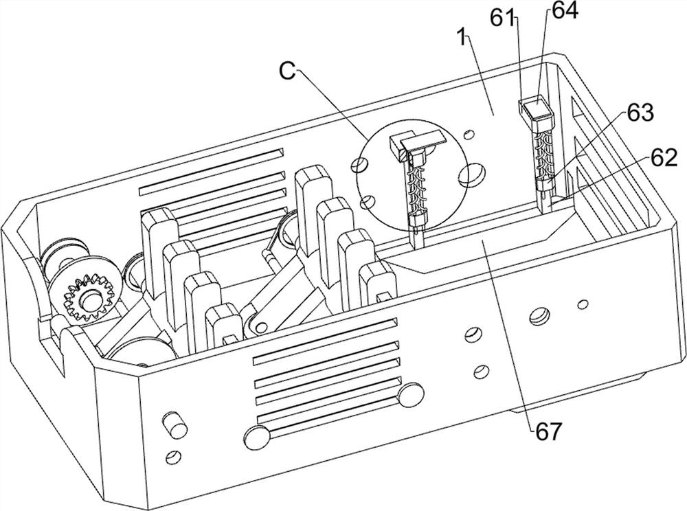
[0044] Based on Example 1 and Example 2, a finite mechanism 6 includes a restricted block 61, a standing plate 62, a mounting block 63, a restricted plate 64, a guide post 65, a second column spring. 66 and ladder block 67, see figure 1 , figure 2 , Figure 9 and Figure 10 As shown, two fixed blocks 61 are mounted by the upper and rear sides of the housing 1, and the mid-pull type, the mid-fixing type, and the top portion of the fixed block 61 is limited to the top of the plate 62. The seat plate 64, the front side two sets of stands are fixed between the trapezoidal block 67, and when the casing 1 drives the ladder block 67 to move to the right, the trapezoidal block 67 can achieve the tiles of the tiles, the front side fixed The bottom side of the block 61 is attached to the front side of the bottom side of the rear fixed block 61 by the welding connection by welding, and the two guide column 65 on each of the fixed block 61 has a mounting block. 63. The upper right side of the m...

Embodiment 3

[0049] Based on Example 1 and Example 2, there is also a scraper mechanism 8, a scraping mechanism 8 includes a finite frame 81, a rotating rod 82, a second belt assembly 83, and a scraper plate 84, see figure 1 , figure 2 and Figure 14 As shown, the finish frame 81 is mounted by the lower portion of the outer left side surface of the housing 1, and the rotation of the rotating rod 82 is rotated between the front and rear two-side limit frame 81, the rotor rod 82 The circumferential uniform intervals are mounted by the welded connection, and when the squeegee plate 84 is rotated, the wiper plate 84 can realize the concrete scraping on the tile, and the front and rear of the rotating rod 82 respectively A second belt assembly 83 is connected between the front and rear sides of the left side shaft 21, and the second belt assembly 83 consists of two pulley and the flat belt, one of which is fixed to the rotating rod 82 and the other pulley fixing sleeve is on the left side. On the sh...


PUM


Abstract

The invention relates to ceramic tile knocking equipment, in particular to ceramic tile knocking equipment for buildings. According to the ceramic tile knocking equipment for the building, the ceramic tiles can be knocked to be compact, the tilted ceramic tiles can be pressed to be compact, and knocking is not affected. Ceramic tile knocking equipment for building comprises a shell, rollers, rotating shafts and the like, the rotating shafts are rotatably connected between the left sides of the lower portions of the front side and the rear side of the shell and between the right lower sides of the front side and the rear side in a penetrating mode, and the rollers are fixedly connected to the front ends and the rear ends of the rotating shafts. A driving mechanism is pulled to be adjusted to a proper position firstly, then the driving mechanism is pushed to drive the device to move rightwards, a rolling wheel rotates forwards to drive a rotating shaft to rotate forwards, the rotating shaft rotates forwards to drive the driving mechanism to operate, the driving mechanism operates to drive a beating mechanism to operate, and the beating mechanism operates to drive rubber to swing up and down to beat a ceramic tile. And the shell further drives the limiting mechanism to operate to compact the tilted ceramic tile, so that the ceramic tile can be compacted, and the tilted ceramic tile can be prevented from influencing compacting.

Description

Technical field [0001] The present invention relates to a tile knocking device, in particular, to a building tile knocking equipment. Background technique [0002] In construction, there is generally needed to lay tiles in the room, which is convenient for future cleaning, and it is convenient for people to walk, but after the tile is laid, in order to avoid mortar is not full, the tile is not tile, and the tile is needed. [0003] The application number is disclosed in China. The front side is opened with a mounting slot, and the driven disc and the active disk are provided in the mounting slot, the driven disk and the active disk are connected to both sides of the mounting groove through the first rotating shaft and the second rotating shaft; the slave side of the driven disc The hammer head is provided, and there is a groove on the end face of the driven disk, and there are a plurality of ratchet holes on the circumferential surface of the groove; the active disk extends into ...

Claims


Application Information

Patent Timeline
Patent Type & Authority Applications(China)
IPC IPC(8): E04F21/22
CPCY02P40/60
Inventor 陈兰英
Owner 陕西铜川煤矿建设有限公司
Why Eureka
Try Eureka