Eureka AIR delivers breakthrough ideas for toughest innovation challenges, trusted by R&D personnel around the world.

Sealing pressure maintaining system of two-stage screw compressor

A screw compressor and compressor technology, applied in the field of compressors, can solve the problems of inconvenient casting, inconvenient maintenance and maintenance, and mismatch of pressure requirements and pressures, so as to ensure the air tightness of the connection, improve the introduction efficiency, and facilitate production. casting effect

Pending Publication Date: 2022-04-05
上海友川技术有限公司
View PDF0 Cites 0 Cited by
  • Summary
  • Abstract
  • Description
  • Claims
  • Application Information

AI Technical Summary

Problems solved by technology

The main body of the traditional two-stage screw compressor adopts an integrated design of high and low pressure stages, so the integrated body is too large, heavy, and complex in structure, and it is not convenient to cast and form when manufacturing the main body, and the integrated body is suitable for high and low pressure. The installation of the inter-stage screw transmission parts is inconvenient, and the maintenance is inconvenient. Therefore, a combined compressor body is required, and the air passage sealing between the connections needs to be ensured; the air compression performance of the traditional two-stage screw compressor is limited. Due to the influence of motor power, the compressor is prone to undercompression or overcompression, especially when the demand pressure at the user end changes, it is more likely to cause the end pressure of the compressor to not match the demand pressure at the user end

Method used


Image

  • Sealing pressure maintaining system of two-stage screw compressor
  • Sealing pressure maintaining system of two-stage screw compressor
  • Sealing pressure maintaining system of two-stage screw compressor

Examples


Embodiment Construction

[0024] In order to describe the technical solution of the present invention more clearly and completely, the present invention will be further described below in conjunction with the accompanying drawings.

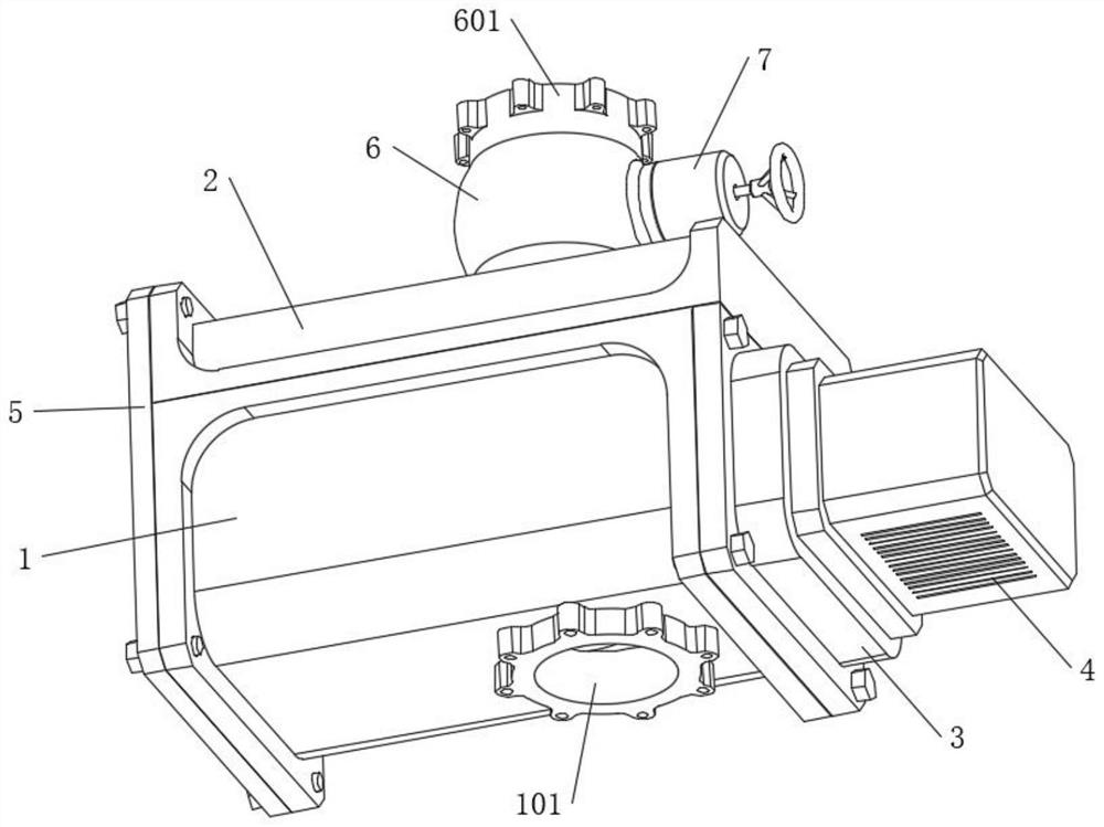
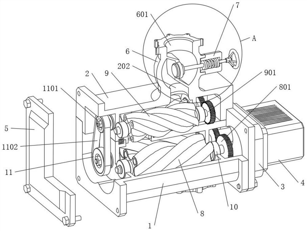
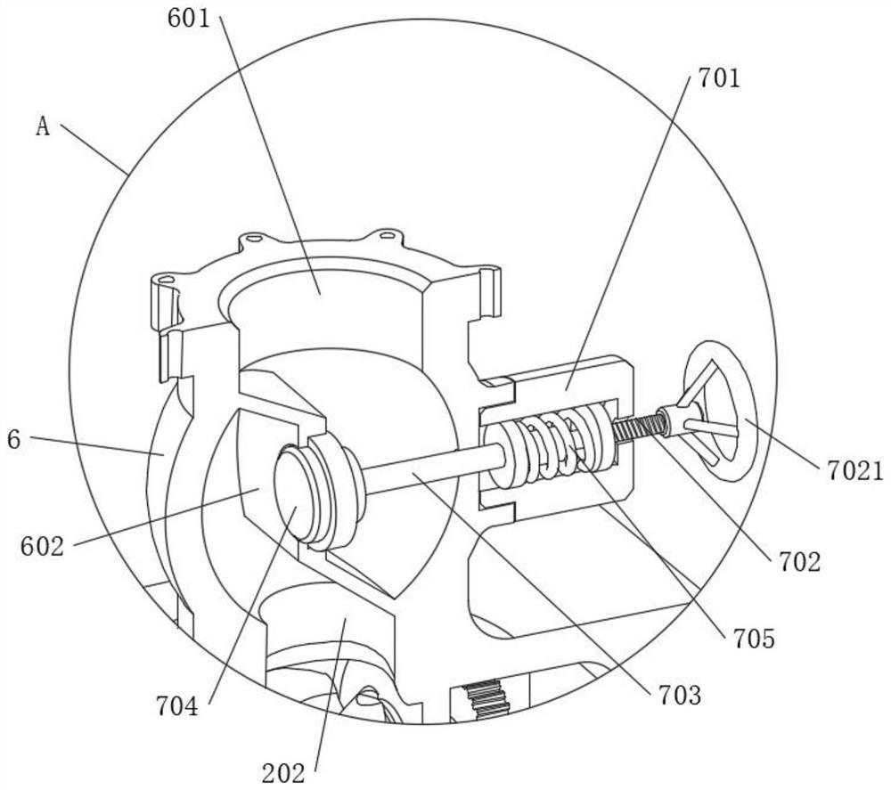
[0025] Please refer to Figure 1-Figure 6 , the present invention proposes a sealed and pressure-maintaining system for a two-stage screw compressor, including a compressor casing body, which consists of a first casing 1, a second casing 2, a first cover 3 and a second The cover 5 is assembled. The inside of the first casing 1 is provided with a pair of first-stage screw rotors 8 arranged in parallel, and the inside of the first casing 1 is provided with a first-stage air cavity matching the pair of first-stage screw rotors 8. One side of the first casing 1 is fixed with a first cover 3 by bolts, and the outer side of the first cover 3 is fixed with a motor 4 by bolts, and the output shaft of the motor 4 is connected to one shaft end of the first-stage screw rotor 8 throug...


PUM


Abstract

The sealing pressure maintaining system of the two-stage screw compressor comprises a compressor shell body, the compressor shell body is formed by assembling a first shell, a second shell, a first sealing cover and a second sealing cover, a pressure adjusting valve seat is arranged on a second-stage air outlet in the top of the second shell, and a pressure adjusting assembly is arranged on one side of the pressure adjusting valve seat. The compressor shell body is formed by assembling the first shell, the second shell, the first sealing cover and the second sealing cover, the assembled structure is convenient to produce and cast, meanwhile, independent assembly of all transmission parts is facilitated, the discharge pressure of gas can be preset by rotating the hand wheel and sealing and opening the gas hole through the jacking block, and the gas discharge efficiency is improved. And the pressure sensor arranged between the pressure regulating screw rod and the connecting end of the ejector rod is used for detecting the pressure of the gas on the ejector block, so that the pressure when the gas is discharged is detected, and the adjustment can be conveniently carried out according to the required gas pressure.

Description

technical field [0001] The invention relates to the technical field of compressors, in particular to a sealing and pressure maintaining system of a two-stage screw compressor. Background technique [0002] A two-stage screw compressor usually includes a two-stage screw compression mechanism, and each screw compression mechanism is composed of a pair of parallel female and male screws that mesh with each other. The main body of the traditional two-stage screw compressor adopts an integrated design of high and low pressure stages, so the integrated body is too large, heavy, and complex in structure, and it is not convenient to cast and form when manufacturing the main body, and the integrated body is suitable for high and low pressure. The installation of the inter-stage screw transmission parts is inconvenient, and the maintenance is inconvenient. Therefore, a combined compressor body is required, and the air passage sealing between the connections needs to be ensured; the ai...

Claims


Application Information

Patent Timeline
Patent Type & Authority Applications(China)
IPC IPC(8): F04C18/08F04C18/16F04C23/00F04C23/02F04C27/00F04C28/24F04C28/28F04C29/00F04C29/12
Inventor 田自强
Owner 上海友川技术有限公司
Why Eureka
Eureka Blog
Learn More