Video coding method and device of camera lighting equipment, equipment and storage medium

A technology for lighting equipment and video coding, applied in digital video signal modification, TV, color TV, etc., can solve problems such as unavailable, achieve load balance, and improve video coding efficiency

Pending Publication Date: 2022-04-05
深圳市海洋王铁路照明技术有限公司 +3
View PDF0 Cites 0 Cited by
  • Summary
  • Abstract
  • Description
  • Claims
  • Application Information

AI Technical Summary

Problems solved by technology

[0003] The object of the present invention is to provide a video encoding method, device, equipment and storage medium for imaging and lighting equipment, aiming at solving the problem that the prior art cannot provide an effective video encoding method to improve the encoding efficiency of multifunctional imaging and lighting equipment

Method used


Image

  • Video coding method and device of camera lighting equipment, equipment and storage medium
  • Video coding method and device of camera lighting equipment, equipment and storage medium
  • Video coding method and device of camera lighting equipment, equipment and storage medium

Examples


Embodiment 1

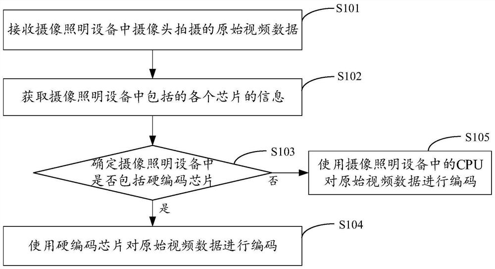
[0022] figure 1 It shows the implementation process of the video coding method for the imaging and lighting equipment provided by the first embodiment of the present invention. For the convenience of description, only the parts related to the embodiment of the present invention are shown, and the details are as follows:

[0023] In step S101, receiving the original video data captured by the camera in the imaging and lighting equipment;

[0024] The embodiments of the present invention are applicable to imaging and lighting equipment, and more specifically, for video encoding captured by imaging and lighting equipment. The imaging and lighting equipment can specifically be wearable imaging and lighting equipment, a work recorder, or a A camera and lighting device, the camera and lighting device includes a lighting device and a camera. When the camera and lighting device is turned on, the camera in the camera and lighting device shoots an image in front of the camera to obtain...

Embodiment 2

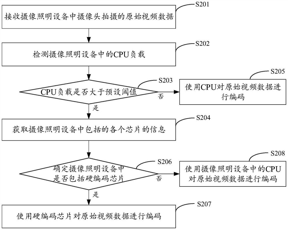
[0035] figure 2 It shows the implementation process of the video encoding method for the imaging and lighting equipment provided by the second embodiment of the present invention. For the convenience of description, only the parts related to the embodiment of the present invention are shown, and the details are as follows:

[0036] In step S201, the original video data captured by the camera in the imaging and lighting equipment is received;

[0037] The embodiments of the present invention are applicable to imaging and lighting equipment, and more specifically, for video encoding captured by imaging and lighting equipment. The imaging and lighting equipment can specifically be wearable imaging and lighting equipment, a work recorder, or a A camera and lighting device, the camera and lighting device includes a lighting device and a camera. When the camera and lighting device is turned on, the camera in the camera and lighting device shoots an image in front of the camera to ...

Embodiment 3

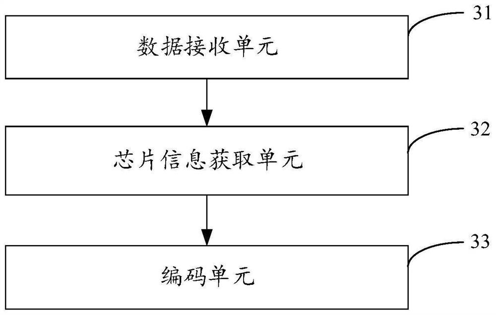
[0050] image 3 The structure of the video coding device of the imaging and lighting equipment provided by the third embodiment of the present invention is shown. For the convenience of description, only the parts related to the embodiment of the present invention are shown, including:

[0051] The data receiving unit 31 is used to receive the original video data captured by the camera in the imaging and lighting equipment;

[0052] The embodiments of the present invention are applicable to imaging and lighting equipment, and more specifically, for video encoding captured by imaging and lighting equipment. The imaging and lighting equipment can specifically be wearable imaging and lighting equipment, a work recorder, or a A camera and lighting device, the camera and lighting device includes a lighting device and a camera. When the camera and lighting device is turned on, the camera in the camera and lighting device shoots an image in front of the camera to obtain the original...


PUM


Abstract

The invention is applicable to the technical field of computers, and provides a video coding method, device and equipment for camera lighting equipment and a storage medium, and the method comprises the steps: receiving original video data shot by a camera in the camera lighting equipment, obtaining the information of each chip included in the camera lighting equipment, and determining whether the camera lighting equipment comprises a hard coding chip or not according to the information of each chip, if so, coding the original video data by using the hard coding chip, otherwise, coding the original video data by using a CPU (Central Processing Unit) in the camera lighting equipment, thereby selecting a corresponding video data coding mode according to the chip configuration in the camera lighting equipment. The load of each chip in the camera lighting equipment is balanced, and the video coding efficiency is improved.

Description

technical field [0001] The invention belongs to the technical field of intelligent lighting, and in particular relates to a video encoding method, device, equipment and storage medium of camera lighting equipment. Background technique [0002] The multi-functional camera and lighting equipment includes lighting devices and cameras, and is suitable for railway transportation shunting and receiving and dispatching operations. Specifically, the multi-functional camera and lighting device can be used for power supply, public works, electrical work on the road, trains and rail cars, and vehicle on-board operations. Mechanics and other places lighting and operation records use. The lighting device in the camera and lighting equipment is used for lighting, and the camera in the camera and lighting equipment is used to take pictures and record videos to record the operation of the user. Therefore, the multifunctional camera and lighting equipment can also be called a multifunctional...

Claims


Application Information

Patent Timeline
Patent Type & Authority Applications(China)
IPC IPC(8): H04N19/42H04N5/225
Inventor 周明杰黄广杰王满红刘月舫蔡小敏
Owner 深圳市海洋王铁路照明技术有限公司
Why Eureka
Try Eureka