
Engine idle speed compensation method and device, electronic equipment and storage medium

An engine idle speed and engine technology, applied in mechanical equipment, engine control, machine/engine, etc., can solve problems such as large engine jitter, customer complaints, and inability to compensate for the engine, and achieve accurate idle speed compensation and avoid large jitter effects.

Active Publication Date: 2022-05-10
GREAT WALL MOTOR CO LTD
View PDF7 Cites 0 Cited by
  • Summary
  • Abstract
  • Description
  • Claims
  • Application Information

AI Technical Summary

Problems solved by technology

[0003] The existing idle speed control is to calculate the engine speed compensation value through the engine water temperature and atmospheric pressure, so as to compensate the engine idle speed. In the case of a large amount, the load on the engine will increase and the engine will vibrate greatly. That is to say, the existing idle speed compensation method cannot accurately compensate the engine.
[0004]The existing idle speed control does not include the power consumption of the whole vehicle into the scope of compensation, resulting in an increase in engine load when the power consumption is large, resulting in increased engine vibration or even flameout, causing customer complain

Method used


Image

  • Engine idle speed compensation method and device, electronic equipment and storage medium
  • Engine idle speed compensation method and device, electronic equipment and storage medium
  • Engine idle speed compensation method and device, electronic equipment and storage medium

Examples


Embodiment Construction

[0032] Specific embodiments of the present disclosure will be described in detail below in conjunction with the accompanying drawings. It should be understood that the specific embodiments described here are only used to illustrate and explain the present disclosure, and are not intended to limit the present disclosure.

[0033] The present disclosure will be described below in conjunction with the following examples.

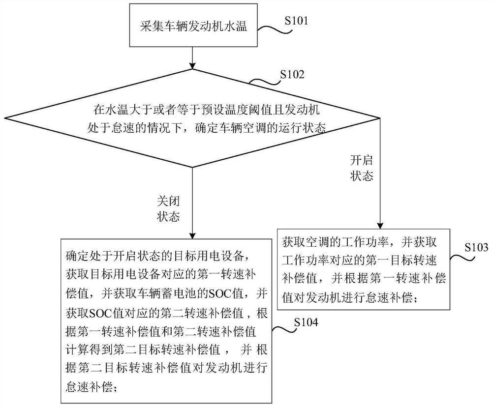
[0034] figure 1 It is a schematic flowchart of an engine idle speed compensation method provided by the present disclosure. Such as figure 1 As shown, the method includes:

[0035] Step S101, collecting the water temperature of the vehicle engine.

[0036] In this step, the water temperature of the engine may be collected by a temperature sensor.

[0037] Step S102, when the water temperature is greater than or equal to the preset temperature threshold and the engine is at idle speed, determine the operating state of the vehicle air conditioner.

[0038] ...


PUM


Abstract

The invention relates to an engine idle speed compensation method and device, electronic equipment and a storage medium. The method comprises the steps that the water temperature of a vehicle engine is collected; when the water temperature is larger than or equal to the preset temperature threshold value and the engine is at the idle speed, the running state of the vehicle air conditioner is determined; under the condition that the running state is the starting state, the working power of a vehicle air conditioner is obtained, a first target rotating speed compensation value corresponding to the working power is obtained, and idle speed compensation is conducted on an engine according to the first target rotating speed compensation value; under the condition that the running state is a closed state, determining target electric equipment in an open state, obtaining a first rotating speed compensation value corresponding to the target electric equipment, obtaining an SOC value of a storage battery of the vehicle, and obtaining a second rotating speed compensation value corresponding to the SOC value, and a second target rotating speed compensation value is calculated according to the first rotating speed compensation value and the second rotating speed compensation value, and idle speed compensation is conducted on the engine according to the second target rotating speed compensation value.

Description

technical field [0001] The present disclosure relates to the field of engine control, and relates to a method, device, electronic equipment and storage medium for engine idle speed compensation. Background technique [0002] Engine idle speed is one of the engine operating conditions. The idle speed condition refers to the state of the engine running without load (i.e. running in neutral). The engine idle speed performance has a great impact on emissions, fuel consumption and comfort. Therefore, the engine idle speed performance is the key to evaluating An important indicator of engine performance. [0003] The existing idle speed control is to calculate the engine speed compensation value through the engine water temperature and atmospheric pressure, so as to compensate the engine idle speed. However, in the case of a large vehicle power consumption, the engine load will increase, and the engine The jitter is large, that is to say, the existing idle speed compensation meth...

Claims


Application Information

Patent Timeline
IPC IPC(8): F02D41/08
CPCF02D41/083
Inventor 魏天伟穆宇刘海松
Owner GREAT WALL MOTOR CO LTD
Learn More