Head chip, liquid ejecting head, liquid ejecting recording apparatus, and method of manufacturing head chip
A chip and liquid technology, applied in the manufacturing field of head chip, liquid jet head, liquid jet recording device and head chip, can solve the problems such as deterioration of ink ejection characteristics, and achieve the effect of suppressing the decline
- Summary
- Abstract
- Description
- Claims
- Application Information
AI Technical Summary
Problems solved by technology
Method used
Image
Examples
Embodiment approach
[0055]
[0056] The printer 1 common to each embodiment will be described.
[0057] figure 1 It is a schematic configuration diagram of the printer according to the embodiment.
[0058] like figure 1 As shown, the printer (liquid jet recording apparatus) 1 of the present embodiment includes a pair of conveying mechanisms 2 and 3 , an ink tank 4 , an ink jet head (liquid jet head) 5 , an ink circulation mechanism 6 , and a scanning mechanism 7 .
[0059] In the following description, it is necessary to use the X, Y, and Z orthogonal coordinate system for the description. In this case, the X direction (second direction) matches the conveyance direction (sub-scanning direction) of the recording medium P (eg, paper, etc.). The Y direction (first direction) corresponds to the scanning direction (main scanning direction) of the scanning mechanism 7 . The Z direction (third direction) shows the height direction (vertical direction) orthogonal to the X direction and the Y direct...
no. 1 approach
[0069]
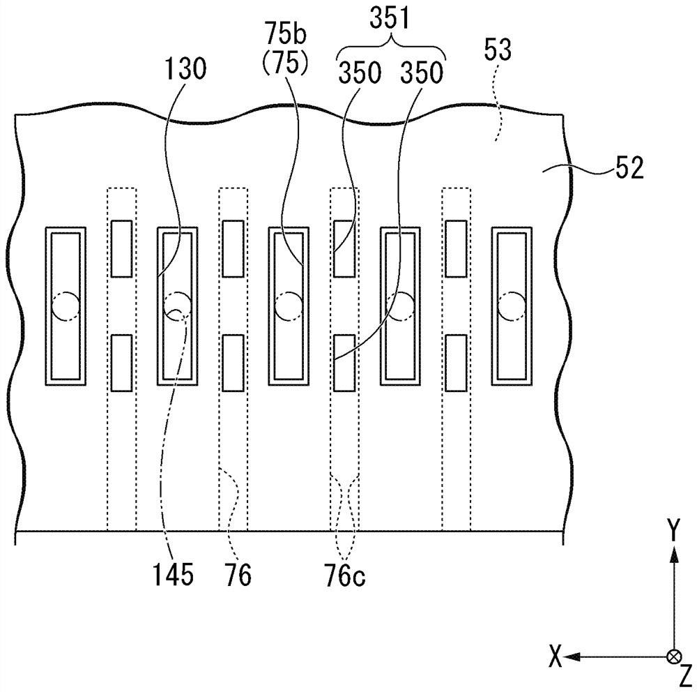
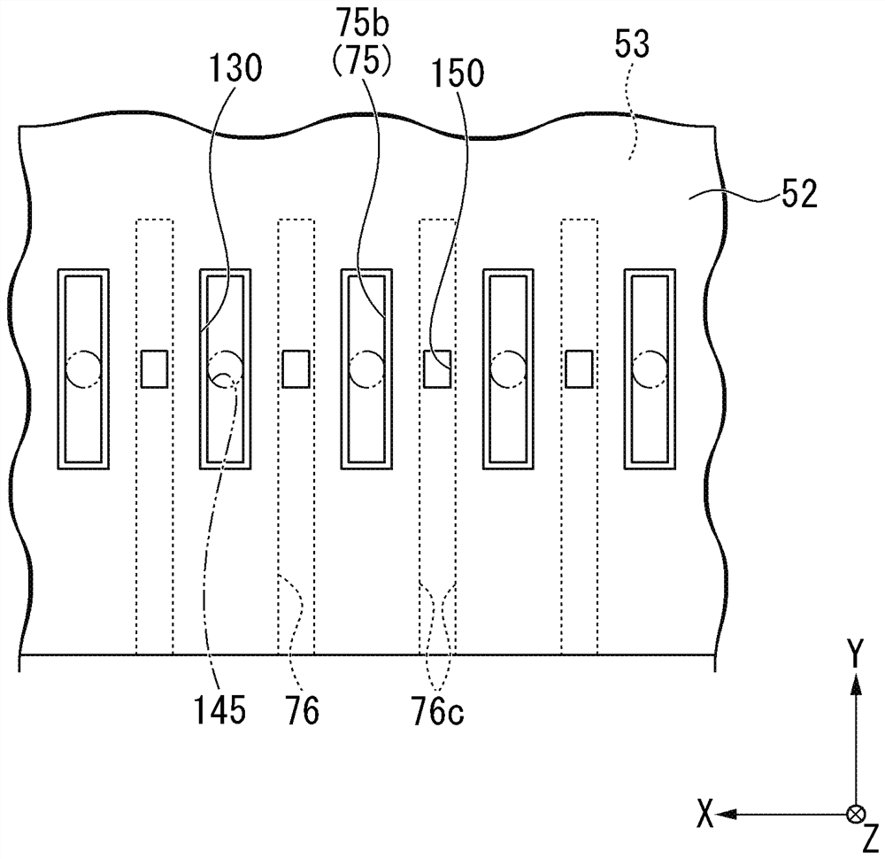
[0070] The head chip 50 of the first embodiment will be described.
[0071] image 3 It is the perspective view which looked at the head chip of 1st Embodiment from -Z side in the state which removed the nozzle plate. Figure 4 It is an exploded perspective view of the head chip of the first embodiment.
[0072] image 3 and Figure 4 The illustrated head chip 50 is a so-called circulating side shooter that circulates ink between the ink tank 4 and the ink tank 4 and discharges the ink from a central portion in the extension direction (Y direction) of the discharge passage 75 to be described later. type head chip. The head chip 50 includes: a nozzle plate (ejection orifice plate) 51 (see Figure 4 ); the intermediate plate 52; the actuator plate 53; and the cover plate 54. The head chip 50 has a structure in which a nozzle plate 51 , an intermediate plate 52 , an actuator plate 53 , and a cover plate 54 are stacked in this order in the Z direction. In the fol...
no. 2 approach
[0137]
[0138] The head chip 50 of the second embodiment will be described.
[0139] Figure 13 It is a bottom view of the actuator board of 2nd Embodiment.
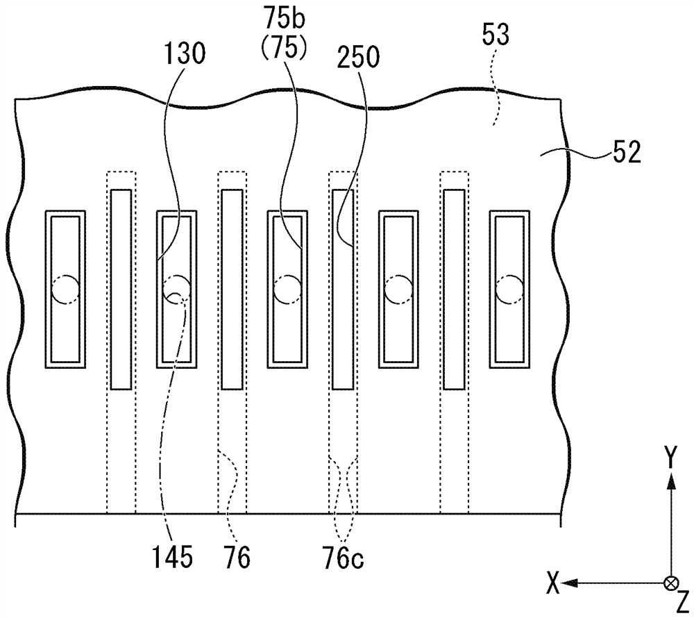
[0140] like Figure 13 As shown, the present embodiment is different from the first embodiment in that the through-hole 250 is provided over the entire length of the Y-direction between the respective through-portions 75b of the pair of discharge passages 75 adjacent to the through-hole 250 in the X-direction. The through hole 250 protrudes outward in the Y direction from both ends of the respective through portions 75b of the pair of discharge passages 75 sandwiching the through hole 250 in a plan view. In other words, the through holes 250 are arranged from one outer side to the other outer side in the Y direction than the respective through portions 75 b of the pair of discharge passages 75 . The through-hole 250 is provided on the inner side in the X direction of the inner surface 76c of the non-discharge passa...
PUM
 Abstract
Description
Claims
Application Information
 - R&D
- Intellectual Property
- Life Sciences
- Materials
- Tech Scout
- Unparalleled Data Quality
- Higher Quality Content
- 60% Fewer Hallucinations
Browse by: Latest US Patents, China's latest patents, Technical Efficacy Thesaurus, Application Domain, Technology Topic, Popular Technical Reports.
© 2025 PatSnap. All rights reserved.Legal|Privacy policy|Modern Slavery Act Transparency Statement|Sitemap|About US| Contact US: help@patsnap.com


