
Disk stack, rotor unit, centrifugal separator, method of providing disk stack and method of providing rotor unit

A technology of centrifugal separator and rotor unit, which is applied in the direction of centrifuge, etc., and can solve problems such as harmful function of centrifugal separator

Pending Publication Date: 2022-06-17
ALFDEX
View PDF12 Cites 0 Cited by
  • Summary
  • Abstract
  • Description
  • Claims
  • Application Information

AI Technical Summary

Problems solved by technology

In rare cases, the discs of the disc stack of the rotor unit can become displaced, which can be detrimental to the function of the centrifuge

Method used


Image

  • Disk stack, rotor unit, centrifugal separator, method of providing disk stack and method of providing rotor unit
  • Disk stack, rotor unit, centrifugal separator, method of providing disk stack and method of providing rotor unit
  • Disk stack, rotor unit, centrifugal separator, method of providing disk stack and method of providing rotor unit

Examples


Embodiment Construction

[0067] Aspects of the present invention will now be described more fully. Like numbers refer to like elements throughout. Well-known functions or constructions are not necessarily described in detail for brevity and / or clarity.

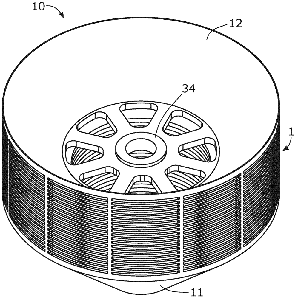
[0068] figure 1 A perspective view of a rotor unit 10 according to some embodiments is shown in an assembled state. The rotor unit 10 is configured to be installed in a separation chamber of a centrifugal separator, such as a crankcase gas separator, as explained further herein. The rotor unit 10 is configured to rotate about the axis of rotation ax during operation in the centrifugal separator in order to separate substances having different densities. According to the illustrated embodiment, the rotor unit 10 comprises a drive shaft 31 for connection to a drive arrangement and a support shaft 32 for connection to a support arrangement, such as a bearing, as explained further herein.

[0069] The rotor unit 10 comprises a disk stack 1 of frusto-c...


PUM


Abstract

A disk stack (1) of frustoconical separation disks (3) is disclosed that is configured to be mounted in a separation chamber (48) of a centrifugal separator (50). The discs (3) are stacked on each other in such a manner that narrow separation spaces (4) are formed between adjacent discs (3). The discs (3) are welded to each other at a radially outer portion (5) of the discs (3). The present disclosure also relates to a rotor unit (10) for a centrifugal separator (50), a centrifugal separator (50) comprising the rotor unit (10), a method (100) of providing a disk stack (1) of frustoconical separation disks (3), and a method (200) of providing a rotor unit (10) for a centrifugal separator (50).

Description

technical field [0001] The present disclosure relates to a disk stack configured as frusto-conical separation disks for installation in the separation chamber of a centrifugal separator, such as a crankcase gas separator. The present disclosure also relates to a rotor unit for a centrifugal separator, a centrifugal separator including the rotor unit, a disc stack providing frusto-conical separation discs configured to be mounted in a separation chamber of the centrifugal separator and a method of providing a rotor unit for a centrifugal separator. Background technique [0002] Mixtures of fluids with different densities can be separated from each other by using centrifugal separators. Centrifugal separators include rotor units that rotate at high rotational speeds to generate centrifugal forces that separate fluids having different densities. The rotor unit may comprise a disk stack of frustoconical separation disks arranged adjacent to each other, with a narrow separation...

Claims


Application Information

Patent Timeline
Patent Type & Authority Applications(China)
IPC IPC(8): B04B5/12B04B7/14
CPCB04B5/12B04B2005/125B04B7/14
Inventor P·琼森
Owner ALFDEX
Learn More