Conveying device

A technology of delivery device and sheath core, applied in stents and other directions, can solve the problems of difficulty in bare wave circles, jumping out of wave peaks, increased difficulty, etc., and achieves the effect of reducing the difficulty of fixing and reducing the release pressure.

Pending Publication Date: 2022-06-21
LIFETECH SCIENTIFIC (SHENZHEN) CO LTD
View PDF0 Cites 0 Cited by
  • Summary
  • Abstract
  • Description
  • Claims
  • Application Information

AI Technical Summary

Problems solved by technology

[0003] Before the stent is implanted into the human tissue, it needs to be compressed and then assembled into the delivery device. When the stent with the bare wave coil is assembled through the fixed anchor and the guide head on the delivery device, it is difficult to complete the bare wave coil on the stent. Hanging on the fixed anchor, especially when assembling the last 1 to 3 peaks on the bare wave ring, it is easy to cause the wave peaks already hung on the fixed anchor to jump out
In addition, during the process of hanging the bare wave coil on the fixed anchor, the bare wave coil is easily deformed, resulting in scrapping of the bracket
Moreover, after the bracket assembly is completed, the contact between the guide head and the fixed anchor on the conveying device is mainly surface contact. This will further increase the difficulty of passing the unhooked bare wave coil through the gap between the fixed anchor and the seeker, which is not conducive to the assembly of other bare wave coils

Method used


Image

  • Conveying device
  • Conveying device
  • Conveying device

Examples


Embodiment 1

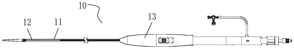
[0033] like Figure 1.1 As shown, delivery device 10 includes catheter 11 , sheath tube assembly 12 and handle 13 . The handle 13 is disposed at the proximal end of the catheter 11 , the sheath core tube assembly 12 passes through the interior of the catheter 11 , and the proximal end of the sheath core tube assembly 12 is fixed on the handle 13 , and the operator can realize the catheter 11 by operating the handle 13 . Relative movement with the sheath core tube assembly 12 . After the stent is assembled on the sheath core tube assembly 12 , the purpose of assembling the stent into the catheter 11 of the delivery device 10 is achieved through the relative movement between the catheter 11 and the sheath core tube assembly 12 in the axial direction.

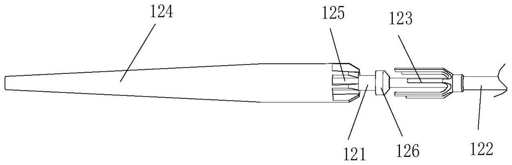
[0034] like Figure 1.2 As shown, the sheath core tube assembly 12 includes an inner sheath core tube 121 and an outer sheath core tube 122 . Specifically, the distal end of the inner sheath core tube 121 protrudes from the dist...

Embodiment 2

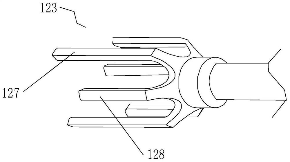
[0057] like Figure 8.1 and Figure 8.2 As shown, in the delivery device of this embodiment, a protrusion 229 is provided on the part of the guide head 224 that is in contact with the fixed anchor 223 . The inner surface is in contact with the upper surface of the protrusion 229, thereby leaving a space for the bare wave ring to move, but the protrusion can also prevent the bare wave ring from detaching from the moving space. At the same time, the protrusions 229 make interference contact between the claw and the receiving portion, which increases the friction between the guide head 224 and the fixing anchor 223, and avoids the separation of the guide head 224 and the fixing anchor 223, which causes the separation of the bare wave ring. Phenomenon.

[0058] Specifically, according to the embodiment of the present application, the outer surface of the accommodating portion 225 facing the inner surface of the claws (that is, the bottom surface of the accommodating portion) is ...


PUM


Abstract

The invention discloses a conveying device which comprises a sheath core tube assembly, the sheath core tube assembly comprises an outer sheath core tube and an inner sheath core tube, the far end of the inner sheath core tube extends out of the far end of the outer sheath core tube and can axially move relative to the outer sheath core tube, a fixing anchor is arranged at the far end of the outer sheath core tube and comprises a plurality of clamping jaws, and the clamping jaws are arranged on the outer sheath core tube. A guide head is arranged at the far end of the inner sheath core tube, a containing part is arranged at the near end of the guide head, the containing part can contain the clamping jaws, and the length of at least one clamping jaw is different from that of the other clamping jaws. According to the conveying device, the multiple wave crests on the support assembling part can be fixed in batches through the clamping jaws with the length differences, so that the fixing difficulty of the multiple wave crests is reduced, meanwhile, the multiple wave crests can be gradually released in batches, and the release pressure of the multiple wave crests at the release moment is reduced.

Description

technical field [0001] The present invention relates to the technical field of interventional medical devices, in particular to a delivery device. Background technique [0002] This section provides merely background information related to the present application and is not necessarily prior art. [0003] Before the stent is implanted into human tissue, it needs to be compressed and assembled into the delivery device. When a stent with a bare wave ring is assembled through the fixed anchor and guide head on the delivery device, it is difficult to fully assemble the bare wave ring on the stent. Hanging on the fixed anchor, especially when assembling the last 1 to 3 wave crests on the bare wave ring, it is easy to cause the wave crests that have been hung on the fixed anchor to jump out. In addition, in the process of hanging the bare wave ring on the fixed anchor, the bare wave ring is easily deformed, which leads to the scrapping of the stent. Moreover, after the stent is ...

Claims


Application Information

Patent Timeline
Patent Type & Authority Applications(China)
IPC IPC(8): A61F2/966A61F2/97
CPCA61F2/966A61F2/97A61F2002/9505
Inventor 刘奎王东辉
Owner LIFETECH SCIENTIFIC (SHENZHEN) CO LTD
Why Eureka
Try Eureka