Cement steel bar bending equipment for construction site

A technology for cement steel bars and construction sites, applied in the field of bending equipment, can solve problems affecting the progress of construction construction, low bending efficiency, steel bar bending, etc., and achieve the effect of increasing stability and improving work efficiency

Active Publication Date: 2022-07-22
珠海园方建设集团有限公司
View PDF10 Cites 0 Cited by
  • Summary
  • Abstract
  • Description
  • Claims
  • Application Information

AI Technical Summary

Problems solved by technology

[0005] In order to overcome the shortcomings of the existing steel bar bending equipment, which is extremely unstable during the bending process of the steel bar, and it is difficult to fully bend the steel bar, resulting in low bending efficiency and affecting the progress of building construction, the technical problem of the present invention is : Provide a kind of cement steel bar bending equipment that has the function of fixing steel bars and can automatically push materials on the construction site

Method used


Image

  • Cement steel bar bending equipment for construction site
  • Cement steel bar bending equipment for construction site
  • Cement steel bar bending equipment for construction site

Examples


Embodiment 1

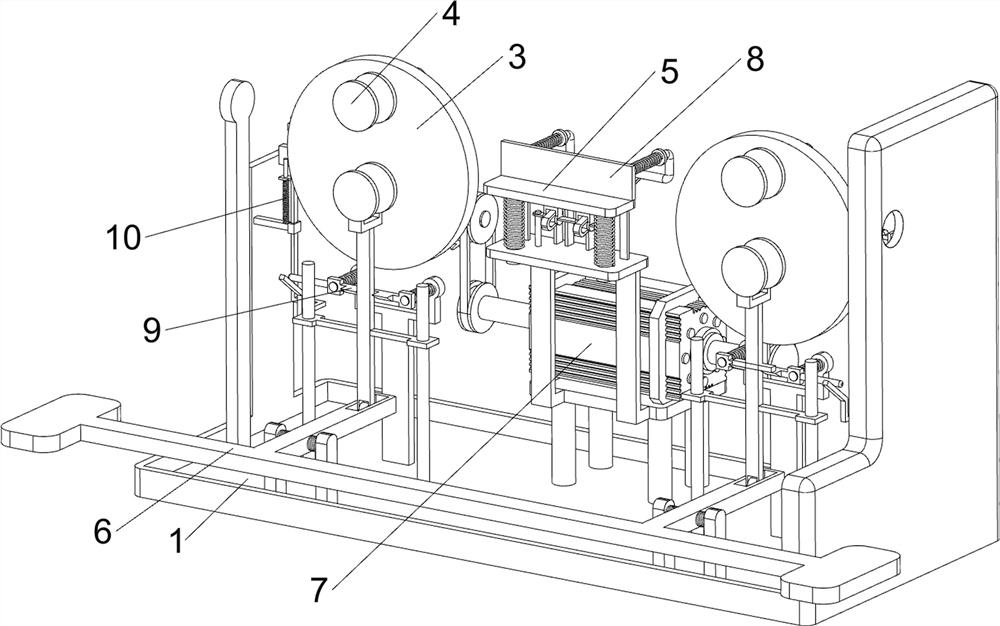
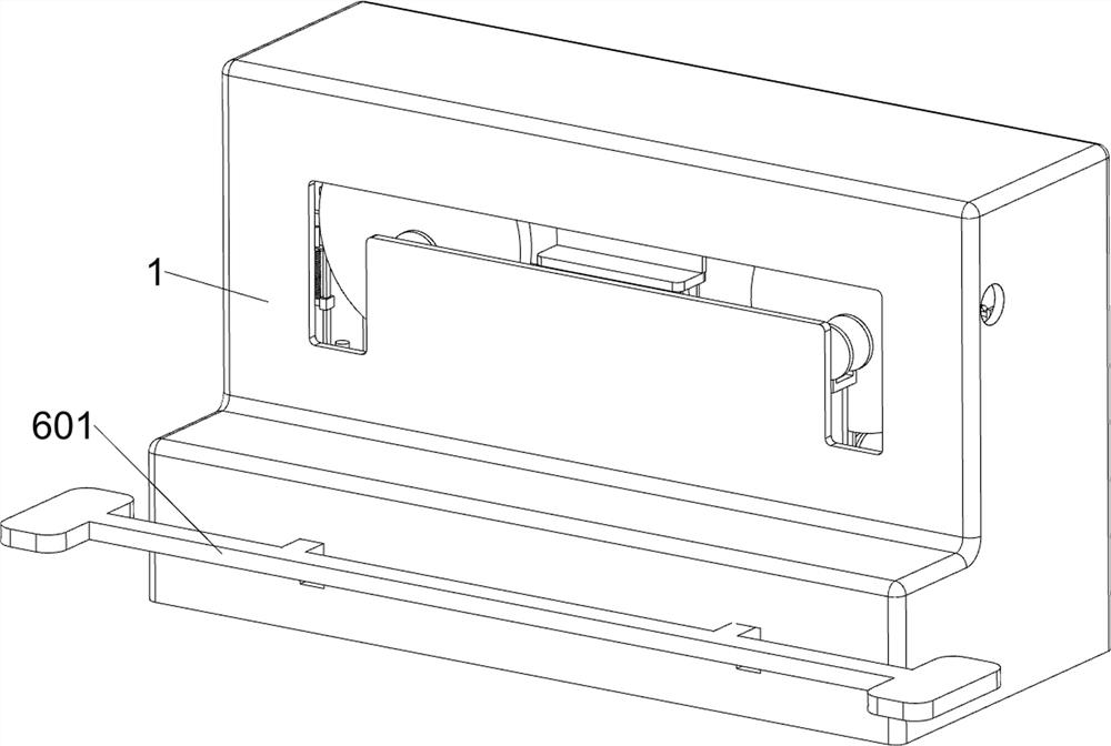
[0028] A cement steel bar bending equipment for construction sites, such as figure 1 , figure 2 , image 3 , Figure 5 and Figure 7 As shown, it includes a box body 1, a first rotating shaft 2, a turntable 3, a bending wheel 4, a buffer assembly 5, a positioning assembly 6 and a driving assembly 7. The inner upper side of the box body 1 is provided with a first rotating shaft 2 symmetrically rotating left and right, A turntable 3 is provided on the first rotating shaft 2, a bending wheel 4 is provided on the front side of the upper part of the turntable 3, a buffer assembly 5 is arranged in the middle of the box body 1, and a positioning assembly 6 is arranged between the turntable 3 and the box body 1, and the first A drive assembly 7 is provided between the rotating shaft 2 and the buffer assembly 5 .

[0029] The buffer assembly 5 includes a support frame 501, a buffer plate 502, a first guide rod 503 and a first spring 504. A support frame 501 is provided in the midd...

Embodiment 2

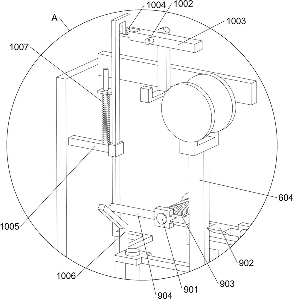
[0034] On the basis of Example 1, as Figure 4 , Image 6 and Figure 8 As shown, it also includes a pusher assembly 8. The pusher assembly 8 includes a rocker 801, a second guide rod 802, a slider 803, a second slider 804, a pusher plate 805 and a second spring 806. The support frame 501 A second guide rod 802 is provided on the left and right sides of the top, a slider 803 is slidably arranged between the second guide rods 802, and the slider 803 cooperates with the buffer plate 502. The rear side of the top of the support frame 501 is provided with a rocker that rotates symmetrically. 801, the rocker 801 is slidably connected to the slider 803, the top and left sides of the support frame 501 are slidably provided with a second slide 804, the second slide 804 is slidably connected to the rocker 801, and the second slide 804 A pushing plate 805 is provided between the front sides, and a second spring 806 is provided between the pushing plate 805 and the second sliding rod 8...


PUM


Abstract

The invention relates to bending equipment, in particular to cement steel bar bending equipment for a construction site. According to the technical aims, the cement reinforcing steel bar bending equipment for the construction site has the reinforcing steel bar fixing effect and can automatically push materials. The invention discloses cement reinforcement bending equipment for a construction site. The two first rotating shafts are symmetrically and rotationally mounted on the upper side of the interior of the box body; the number of the rotating discs is two, and the rotating discs are both installed on the first rotating shaft. The two bending wheels are both mounted on one side of the upper part of the turntable; the buffering assembly is installed in the middle of the interior of the box body. According to the steel bar bending device, the bending wheel continues to rotate outwards, a volute spiral spring deforms, the bending wheel bends a steel bar at the moment, when the steel bar is bent, a buffer plate and a first guide rod move downwards, the buffer plate plays a role in buffering, and a positioning wheel can better bend the steel bar.

Description

technical field [0001] The invention relates to a bending device, in particular to a cement steel bar bending device for a construction site. Background technique [0002] With the continuous development of the construction industry, steel bars are an indispensable material on construction sites. In the process of using steel bars, it is necessary to bend the steel bars to facilitate the later use of the building. [0003] At present, in the existing steel bar bending equipment, it is very unstable during the bending process of the steel bar, and it is difficult to fully bend the steel bar, resulting in low bending efficiency and affecting the progress of the building construction. After the steel bar is bent, manual labor is required Manually take out the bent steel bars. During the process of taking out the steel bars, there are potential safety hazards. People are slightly inattentive, and it is easy to scratch people's hands. [0004] In summary, it is necessary to desi...

Claims


Application Information

Patent Timeline
Patent Type & Authority Applications(China)
IPC IPC(8): B21F1/00
CPCB21F1/008Y02P70/10
Inventor 盘三妹
Owner 珠海园方建设集团有限公司
Why Eureka
Try Eureka