A kind of steel bending device for engineering construction

A technology for steel bar bending and engineering construction, applied in the field of construction machinery, can solve the problems of no angle marking line, inability to meet, low work efficiency, etc., and achieve the effect of convenient steel bar bending work, simple and novel structure, and high work efficiency

Active Publication Date: 2019-11-15
中国机械工业第四建设工程有限公司
View PDF8 Cites 1 Cited by
  • Summary
  • Abstract
  • Description
  • Claims
  • Application Information

AI Technical Summary

Problems solved by technology

In many construction sites, it is necessary to bend steel bars to meet some construction needs. Most of the existing operation methods use manpower to bend, and some thicker steel bars need manpower and some simple equipment to bend when bending, but manual The bending of steel bars not only consumes a lot of manpower and has low work efficiency, but also takes up a lot of construction space, which cannot meet the actual needs. Moreover, the existing steel bar bending machines do not have angle marking lines, etc., resulting in the staff not being able to work well. To fully understand the bending angle of the steel bar, the steel bar can only be bent to a certain fixed value of the bending radius of curvature, resulting in a narrower application range of the bent steel bar

Method used


Image

  • A kind of steel bending device for engineering construction
  • A kind of steel bending device for engineering construction
  • A kind of steel bending device for engineering construction

Examples


Embodiment Construction

[0020] The following will clearly and completely describe the technical solutions in the embodiments of the present invention with reference to the accompanying drawings in the embodiments of the present invention. Obviously, the described embodiments are only some, not all, embodiments of the present invention. Based on the embodiments of the present invention, all other embodiments obtained by persons of ordinary skill in the art without making creative efforts belong to the protection scope of the present invention.

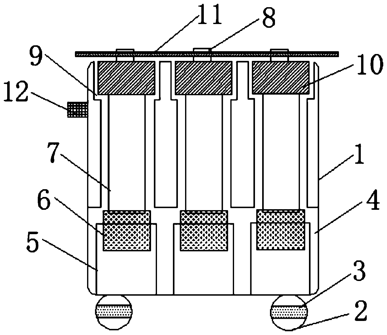
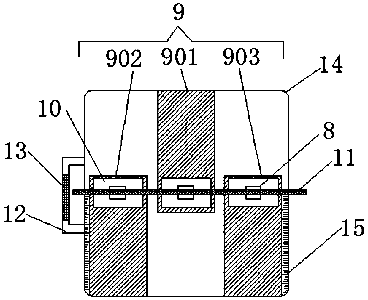
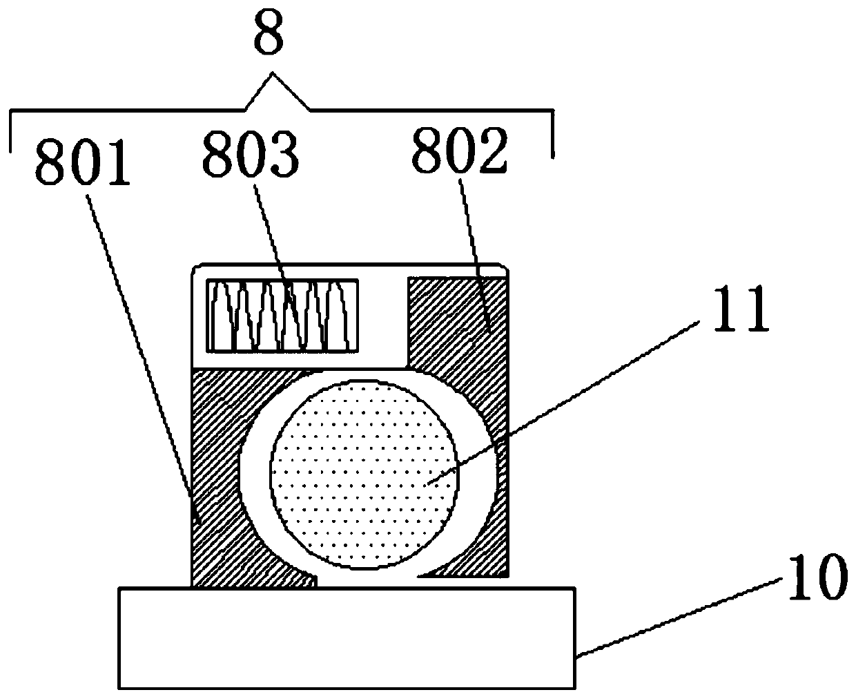
[0021] see Figure 1-3 A technical solution provided by the present invention: a steel bar bending device for engineering construction, including a workbench 1 and a roller 2, the roller 2 is installed at the lower end of the workbench 1, and the worker can move the workbench 1 to the Designated position, carry out the bending work of steel bar 11, the inner side of the lower end of described workbench 1 is provided with cavity 4, and the inner side of describ...


PUM


Abstract

The invention discloses a steel bar bending device for engineering construction. The steel bar bending device comprises a worktable and rolling wheels, wherein the rolling wheels are mounted at the lower end of the worktable; a cavity is arranged at the inner side of the lower end of the worktable; hydraulic air cylinders and pistons are mounted at the inner side of the cavity; the pistons are arranged at the inner sides of the hydraulic air cylinders; supporting rods are arranged at the upper ends of the pistons; sliding blocks are arranged at the upper ends of the supporting rods; sliding grooves adaptive to the sliding blocks are formed in the inner side of the upper end of the worktable; locking structures are mounted at the upper ends of the sliding blocks; steel bars are locked at the inner sides of the locking structures; an angle labeling line is arranged at the upper end of the worktable. According to the steel bar bending device for the engineering construction, the handle and the rolling wheels are used for moving the worktable to an appointed position to carry out bending work of the steel bars and the hydraulic air cylinders drive the pistons and the supporting rods tomove, so that the sliding blocks are driven to move; the angle labeling line is used for representing the bending degree of the steel bars. The steel bar bending device for the engineering construction is novel in structure and high in working efficiency.

Description

technical field [0001] The invention belongs to the technical field of engineering machinery, and in particular relates to a steel bar bending device for engineering construction. Background technique [0002] With the gradual development of my country's economic construction, large-scale construction projects are being carried out all over the country to build various residential buildings, office buildings, road works and other projects under construction. A large number of steel bars are bent. In many construction sites, it is necessary to bend steel bars to meet some construction needs. Most of the existing operation methods use manpower for bending, and some thicker steel bars need manpower and some simple equipment for bending when bending, but manual The bending of steel bars not only consumes a lot of manpower and has low work efficiency, but also takes up a lot of construction space, which cannot meet the actual needs. Moreover, the existing steel bar bending machin...

Claims


Application Information

Patent Timeline
Patent Type & Authority Patents(China)
IPC IPC(8): B21F1/00
CPCB21F1/004
Inventor 缪湘湘王杰赵广龙
Owner 中国机械工业第四建设工程有限公司
Why Eureka
Try Eureka