Engineering supervision field detection recording device
A technology of on-site detection and recording device, applied in the direction of measurement device, measurement value recording, measurement instrument, etc., can solve the problems of inconvenient holding and moving of recording device, cumbersome recording process, time-consuming, etc., and achieve faster and more efficient recording. Direct, record the effect of a comprehensive project and a wide range of assembly
- Summary
- Abstract
- Description
- Claims
- Application Information
AI Technical Summary
Problems solved by technology
Method used
Image
Examples
Embodiment 1
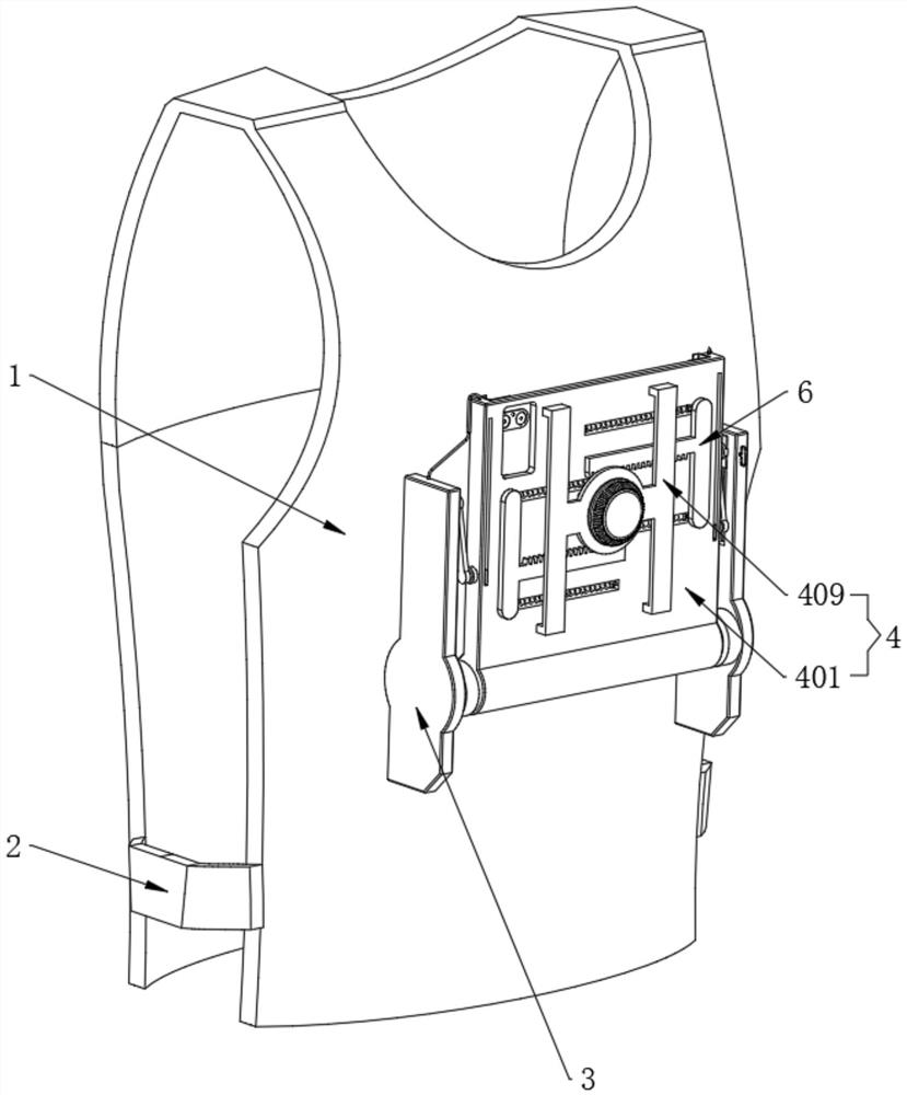
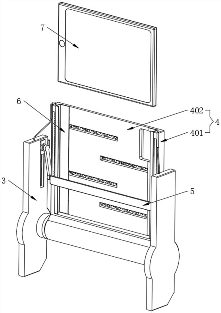
[0041] Refer to the attached Figure 5 The rigid plastic frame 3 also includes a guide frame body 301. The inner sides of the two guide frame bodies 301 are fixedly provided with inner guide grooves 302, and the inner guide grooves 302 are slidably installed with inner sliders 303. Including a combination frame 401, the bottom of the combination frame 401 is rotatably connected with the two guide frame bodies 301, and the outer walls on both sides of the combination frame 401 are rotatably connected with adapter arms 408, and the ends of the two adapter arms 408 are respectively connected with the two inner The sliding block 303 is connected in rotation, a locking pin 304 is movably inserted into the inner side of a guide frame body 301, one end of the locking plug 304 is movably engaged with the inner slider 303, and the other end of the locking plug 304 is located inside the guide frame body 301. Spring 1 305, and one end of the locking pin 304 away from the inner slider 303...
Embodiment 2
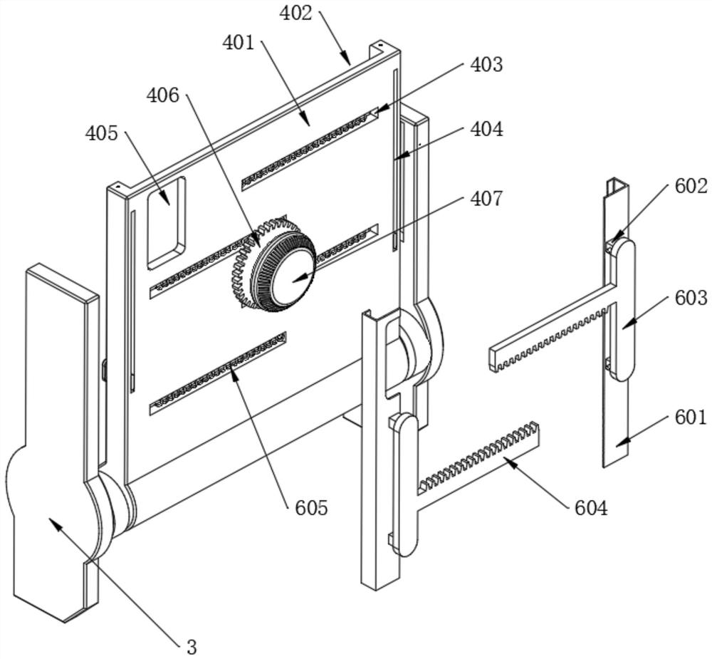
[0044] Refer to the attached image 3 , a side of the combination frame 401 close to the wearing vest 1 is fixedly opened with an embedded groove 402, the surface of the combination frame 401 is staggered and equally spaced with spring grooves 403, and both sides of the combination frame 401 are fixed with sliding grooves 404. A camera opening 405 is fixedly opened on a corner of the surface of the frame 401, an outer frame plate 409 is fixedly arranged on the surface of the combination frame 401 away from the wearing vest 1, the center of the outer frame plate 409 is rotatably installed with a gear 406, and one side of the gear 406 is fixedly connected There is a runner 407 .
[0045] Refer to the attached image 3 , the clamping structure 6 also includes a clamping groove rod 601, two clamping groove rods 601 are symmetrically assembled on both sides of the interior of the embedding groove 402, and both ends of one side of the clamping groove rod 601 are fixedly provided wi...
Embodiment 3
[0048] Refer to the attached Figure 4 , the stain removing structure 5 also includes an inner wiping plate 501, the surface of the inner wiping plate 501 close to the combination frame 401 is fixedly provided with a wiping cotton 502, and both ends of the inner wiping plate 501 are fixedly provided with end sliders 503, and the two ends are sliding The blocks 503 are respectively slidably installed inside the two sliding grooves 404, one side of the end slider 503 is fixedly connected with a traction steel wire 504, and both ends of the top of the combined frame 401 are fixedly provided with a wire tube 506, and the traction steel wire 504 The end passes through the wire tube 506 and is fixedly connected with the top of the guide frame body 301. The sliding groove 404 is located on the outer surface of the traction steel wire 504 and is provided with a second spring 505. During the process of rotating and opening the assembly frame 401, the assembly frame 401 The straight-lin...
PUM
 Abstract
Description
Claims
Application Information
 - R&D
- Intellectual Property
- Life Sciences
- Materials
- Tech Scout
- Unparalleled Data Quality
- Higher Quality Content
- 60% Fewer Hallucinations
Browse by: Latest US Patents, China's latest patents, Technical Efficacy Thesaurus, Application Domain, Technology Topic, Popular Technical Reports.
© 2025 PatSnap. All rights reserved.Legal|Privacy policy|Modern Slavery Act Transparency Statement|Sitemap|About US| Contact US: help@patsnap.com


