
Portable physical cooling device for department of pediatrics

A physical cooling and portable technology, which can be applied to heating appliances for treatment, cooling appliances for treatment, contraceptives, etc. Effect

Pending Publication Date: 2022-08-09
肖玉平
View PDF1 Cites 0 Cited by
  • Summary
  • Abstract
  • Description
  • Claims
  • Application Information

AI Technical Summary

Problems solved by technology

[0005] In order to overcome the disadvantages of poor cooling effect of existing pediatric clinical physical cooling devices, and the need for manual hand-held, time-consuming and labor-intensive shortcomings, the technical problem of the present invention is to provide a device that can physically cool down through wind power, has a good cooling effect, and does not require manual hand-holding. At the same time, it is a detachable and portable pediatric portable physical cooling device

Method used


Image

  • Portable physical cooling device for department of pediatrics
  • Portable physical cooling device for department of pediatrics
  • Portable physical cooling device for department of pediatrics

Examples


Embodiment 1

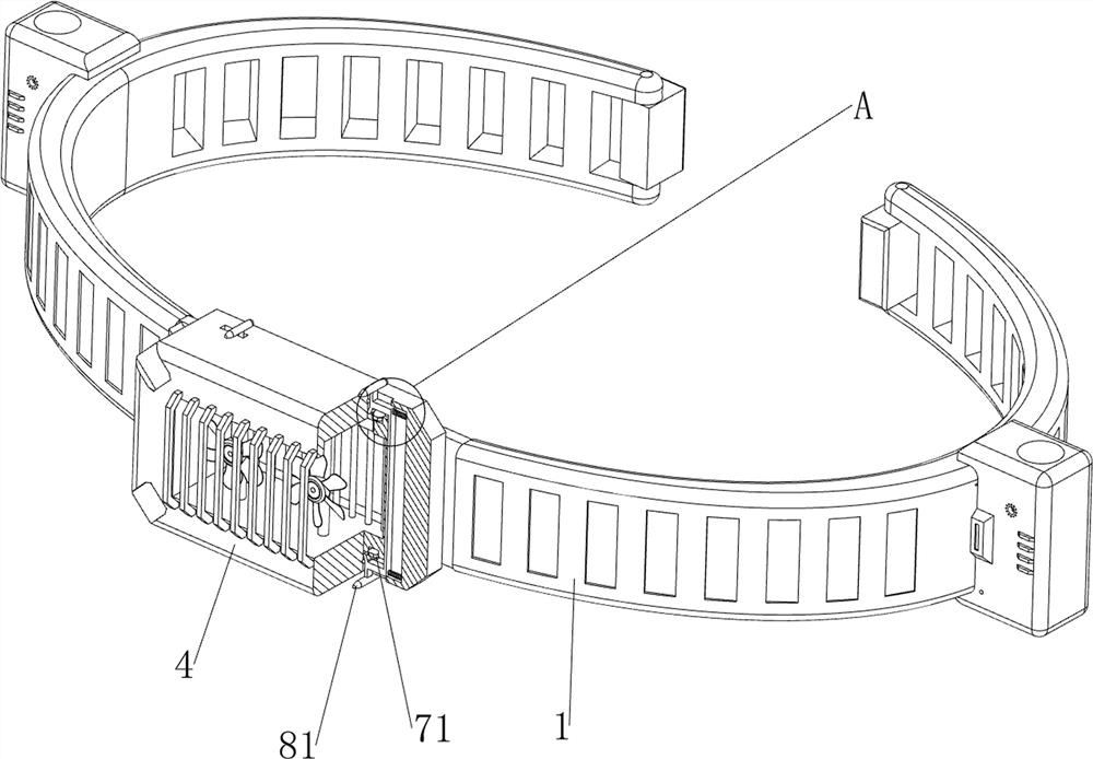
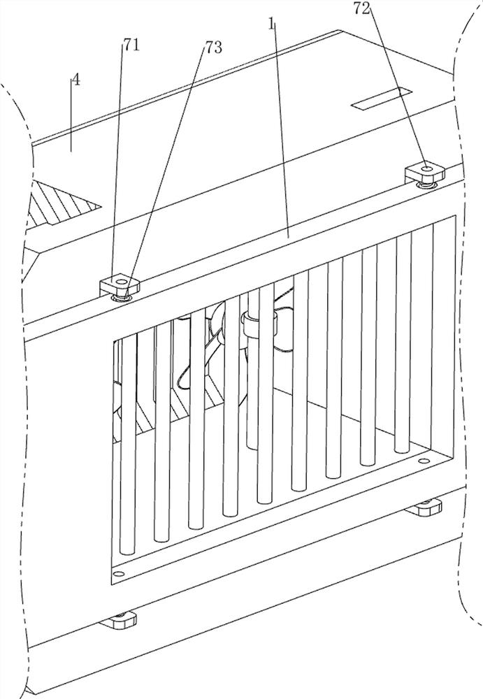
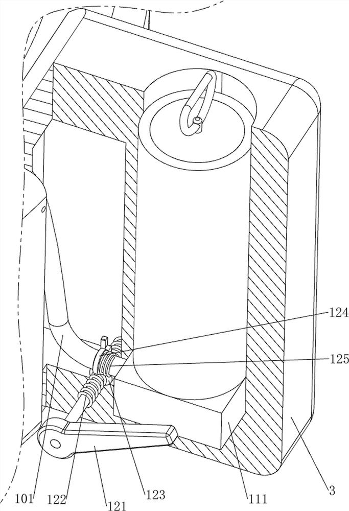
[0038] A pediatric portable physical cooling device such as Figure 1-6 As shown, it includes a belt 1, a first rotating plate 2, a first outer frame 3, a second outer frame 4, a first rotating shaft 5, a fan 6, a fixing mechanism 7 and a dismounting mechanism 8, and the belt 1 is used to be fixed on the child's On the forehead, the whole device is fixed. The left and right sides of the back of the belt 1 are connected with a first turning plate 2 in a rotatable manner. The left and right sides of the belt 1 are provided with a first outer frame 3 through bolts. There is a fixing mechanism 7, the front side of the fixing mechanism 7 is clamped with a second outer frame 4, the left and right sides of the second outer frame 4 are connected with a first rotating shaft 5, the first rotating shaft 5 is provided with a fan 6, and the first rotating shaft 5. The rotation of the fan 6 can adjust the direction of the fan 6. The fan 6 is used to physically cool the child. The second out...

Embodiment 2

[0043] On the basis of Example 1, as figure 2 , Figure 7 and Figure 8 As shown, it also includes a steering mechanism 9, which can adjust the steering of the fan 6. The steering mechanism 9 includes a second rotating shaft 91, a second rotating plate 92 and a set of gears 93, and the middle of the second outer frame 4 is rotatably connected with a second rotating shaft 91. The top of the second rotating shaft 91 is provided with a second rotating plate 92. By rotating the second rotating plate 92, the second rotating shaft 91 is driven to rotate. The upper parts of the two first rotating shafts 5 and the second rotating shaft 91 are provided with gears 93. Three Gear 93 meshes.

[0044] If the rotation of the fan 6 needs to be adjusted, the second rotating plate 92 can be manually rotated. The rotation of the second rotating plate 92 drives the second rotating shaft 91 and the gear 93 to rotate, so that the first rotating shaft 5 and the fan 6 rotate, so that the fan 6 fa...


PUM


Abstract

The invention relates to a physical cooling device, in particular to a portable physical cooling device for the department of pediatrics. The portable physical cooling device for the pediatric department aims at achieving the technical purposes that physical cooling can be achieved through wind power, the cooling effect is good, manual hand holding is not needed, and meanwhile the portable physical cooling device for the pediatric department is detachable and convenient to carry. According to the technical scheme, the portable physical cooling device for the pediatric department comprises a waistband, first rotating plates, first outer frames, second outer frames, a fixing mechanism and the like, the first rotating plates are rotationally connected to the left side and the right side of the rear portion of the waistband, the first outer frames are arranged on the left side and the right side of the waistband, and the fixing mechanism is arranged in the middle of the front portion of the waistband; a second outer frame is clamped to the front side of the fixing mechanism. The mode that the first sliding rods are moved to extrude the limiting blocks is adopted, the limiting blocks can be separated from the second outer frame, and therefore people can conveniently detach the second outer frame, and people can conveniently carry the device.

Description

technical field [0001] The invention relates to a physical cooling device, in particular to a pediatric portable physical cooling device. Background technique [0002] In pediatrics, it is very common for children to have high fever. Generally, children are given antipyretics or injections to reduce fever. However, if they take medicines frequently, it is easy to reduce the resistance of children. Medical staff will generally cool children physically and use wet compresses. Towels and alcohol wipes cool down, and alcohol wipes can easily cause children's foreheads to turn red. [0003] The patent application number is CN201920458416.6 A physical cooling device for pediatric clinical use, comprising a support plate, characterized in that: the support plate is provided with a symmetrical trapezoidal chute, and the support plate is provided with a symmetrical groove, so the One side of the support plate is fixedly connected to one side of the two vertical rods of the door-shap...

Claims


Application Information

Patent Timeline
Patent Type & Authority Applications(China)
IPC IPC(8): A61F7/00
CPCA61F7/00A61F2007/0007A61F2007/0063
Inventor 肖玉平
Owner 肖玉平
Learn More