Electric lamp

A technology of protective cover and light source, applied in the field of type lamp

Inactive Publication Date: 2004-06-09
KONINKLIJKE PHILIPS ELECTRONICS NV
View PDF2 Cites 0 Cited by
  • Summary
  • Abstract
  • Description
  • Claims
  • Application Information

AI Technical Summary

Problems solved by technology

Although the closed end of the boot provides additional protection for the bulb in the event of a bubble failure, multiple soldering steps are required to connect the light source to the input leads and to achieve boot support
In addition, since the protective cover must be supported by means of support straps close to the closed end, for stability the corresponding mounting legs must carry the lamp bulb

Method used


Image

  • Electric lamp
  • Electric lamp
  • Electric lamp

Examples


Embodiment Construction

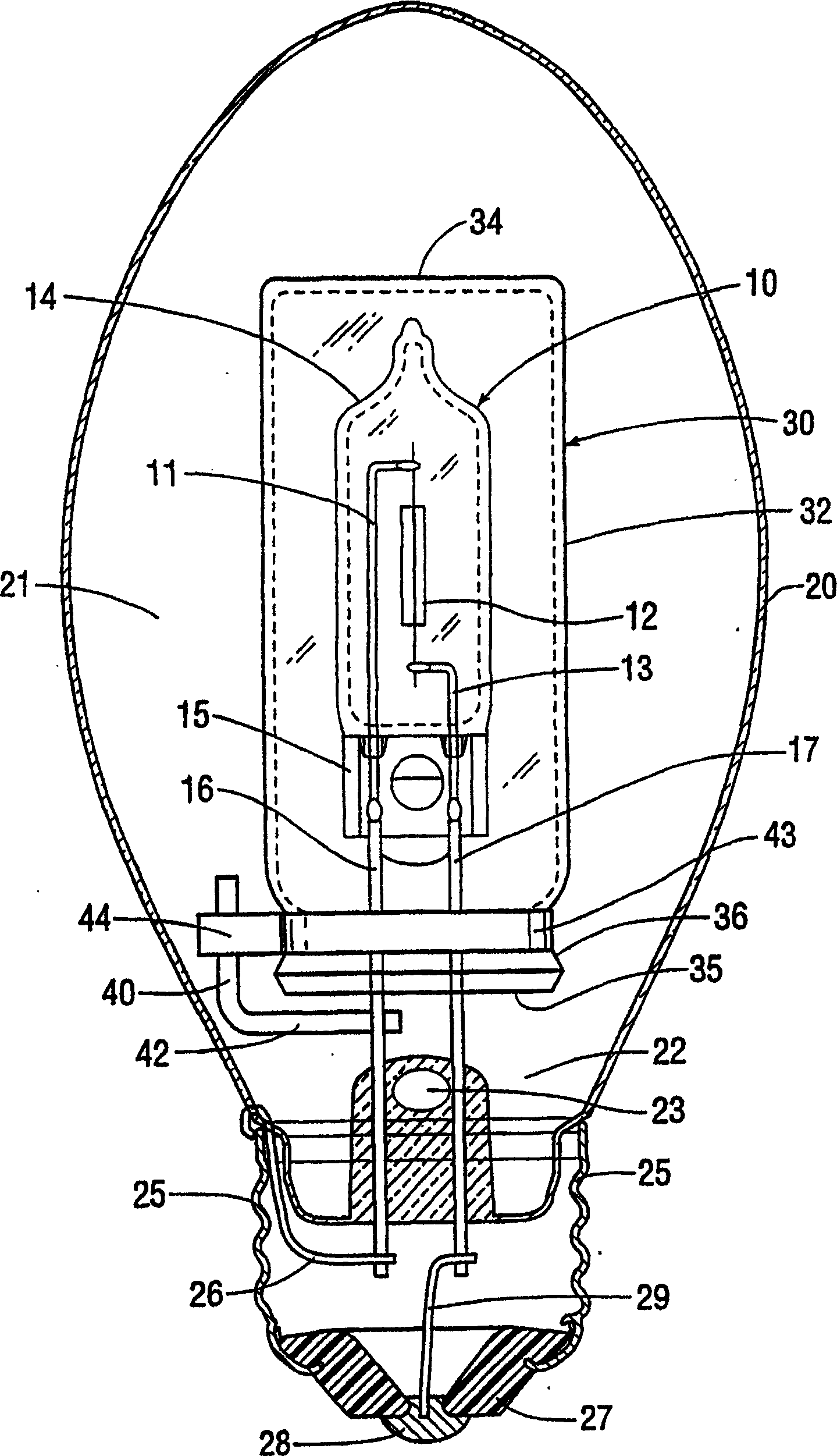
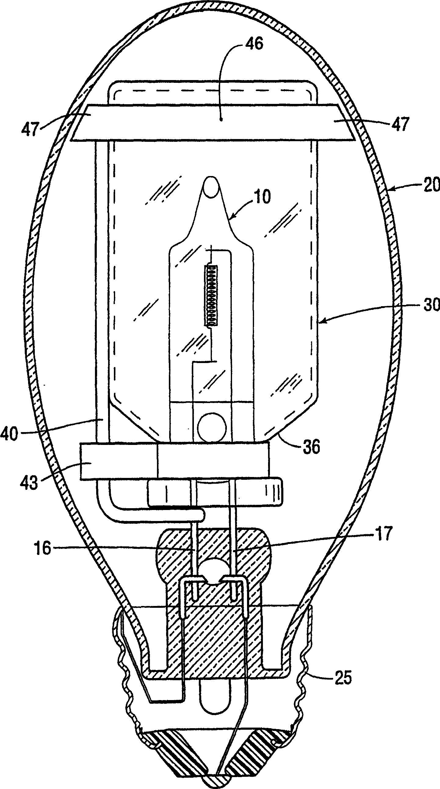
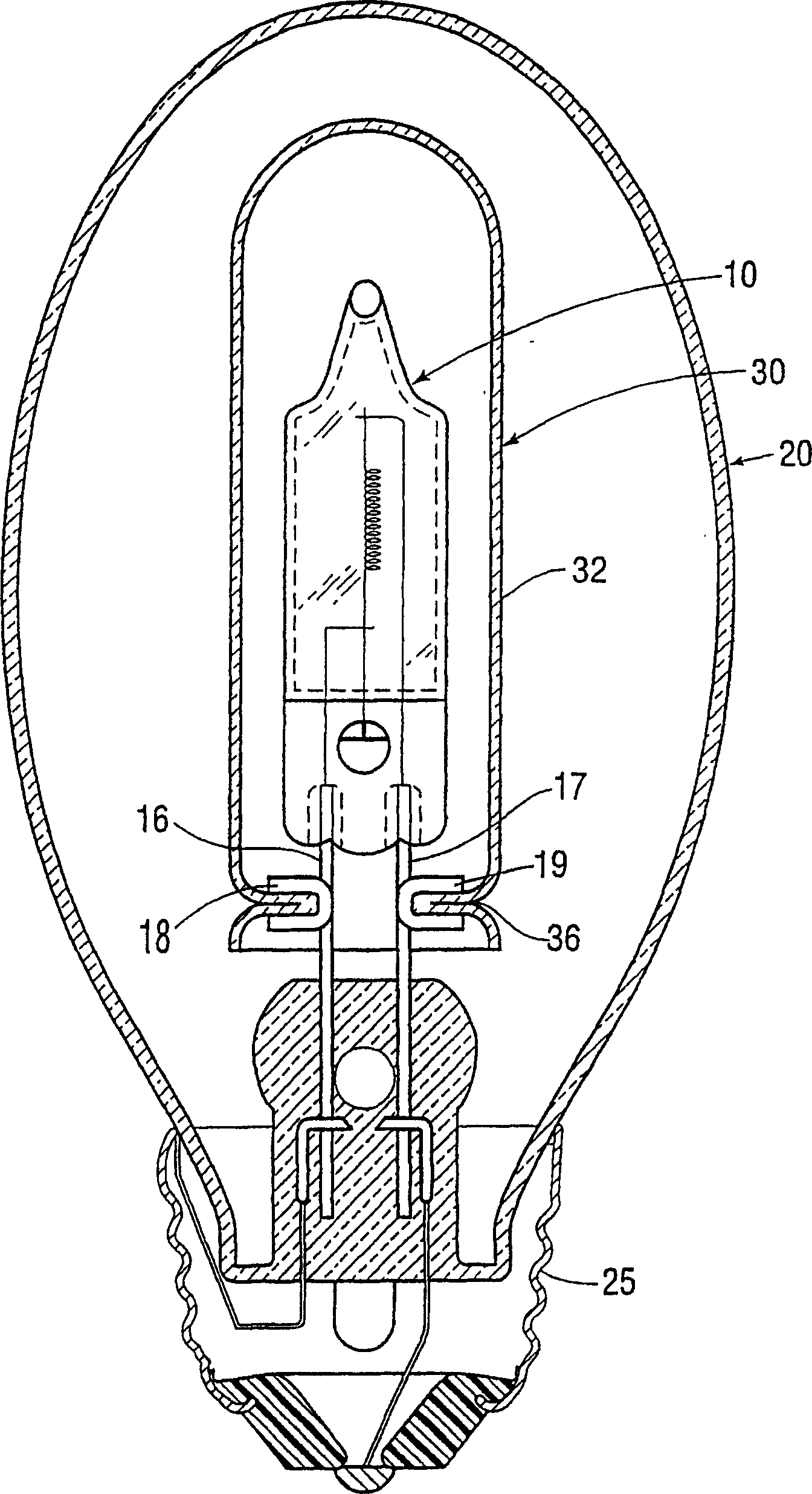
[0018] refer to figure 1 The light source 10 is a tungsten-halogen incandescent lamp, which has a first inner lead 11, a second inner lead 13 and a tungsten filament 12 therebetween. The bulb 14 has at one end a clamp 15 in which the inner leads 11, 13 are connected in known manner to respective outer leads 16, 17 to facilitate sealing. The outer leads 16 , 17 extend outward from the clamp 15 substantially in parallel.

[0019] A glass bulb 20 surrounds a filling space 21 and is fixed to a glass stem 22, which is formed with a suction port 23, which is closed after pumping. The outer leads 16, 17 are sealed directly to the glass stem 22 without any bending or welding, so they are the same leads as the input leads in the glass stem. A conductive base 25 is fixed to the bulb 20 and is electrically connected to the first outer lead 16 through the base lead 26 . A conductive center contact 28 is secured to base 25 by insulating epoxy 27 and is electrically connected to second l...


PUM


Abstract

A light source (10) includes a bulb (14) having a pair of outer leads (16, 17) extending therefrom in parallel and sealed directly in the glass stem (22), whereby the outer leads (16, 17) and the input leads in the glass stem (22) are the same. A protective shroud (30) surrounding the light source (10) may be supported by a metal member (40) welded to one of the leads between the stem (22) and the light source (10). The metal member carries a strap (43) seated in a circumferential constriction (36) of the shroud (30), which may be a commercially available glass vial. In another embodiment, horseshoe-shaped members (18, 19) having mutually opposed concavities are welded to respective leads (16, 17) and a shroud (30) is locally heated to form a circumferential constriction (36) which shrinks into the concavities, thereby supporting the shroud internally. Alternatively, the shroud can be shrunk directly against the pinch (15) so that it converges toward the open end (35) where it engages leads (16, 17).

Description

technical field [0001] The present invention relates to a lamp of the type having: a light source element comprising a bulb having a pair of outwardly extending outer leads; a glass envelope surrounding the light source; and a glass stem, It is fixed to the glass bulb. A pair of input leads encapsulated in the glass stem is electrically connected to the outer leads of the light source. More particularly, the present invention relates to lamps having a protective cover surrounding the light source. Background technique [0002] US Patent 5670840 discloses a lamp having a tungsten-halogen light source with filaments connected to electrodes connected to foils in fixtures at the ends of a bulb and having external leads connected to the foils. The outer leads are soldered to mounting legs encapsulated in glass stems, which act as input leads. One of the mounting legs supports a tubular glass or quartz protective cover that surrounds the light source and protects the glass enve...

Claims


Application Information

Patent Timeline
Patent Type & Authority Patents(China)
IPC IPC(8): H01J61/50H01J61/34H01J61/36H01K1/40
CPCH01J61/34H01J61/36
Inventor P·约翰森M·莫雷尔C·海曼斯
Owner KONINKLIJKE PHILIPS ELECTRONICS NV
Why Eureka
Try Eureka