
Speedometer mounting structure of automatic bicycle

A technology for automatic two-wheeled vehicles and speedometers, which is applied to bicycle accessories, bicycle control systems, bicycle auxiliary equipment, etc., can solve the problems of large number of parts, increased installation man-hours, and influence on the design effect of automatic two-wheeled vehicles. The effect of smoothing the shape lines and improving the design effect

Inactive Publication Date: 2004-12-29
HONDA MOTOR CO LTD
View PDF1 Cites 0 Cited by
  • Summary
  • Abstract
  • Description
  • Claims
  • Application Information

AI Technical Summary

Problems solved by technology

[0005] Generally, a headlight is installed in front of the front fork 1, and the headlight greatly affects the design effect of the motorcycle
[0006] However, in the above-mentioned installation structure, since the speedometer 4 is protrudingly fixed in front of the front fork 1, the position of the speedometer is arranged near the top of the headlight, which hinders the aforementioned design effect obtained by the headlight.
[0007] Also, when installing the speedometer 4, since an additional installation member 3 is required, the number of parts is large, and at the same time, there is a problem that the number of man-hours for installation increases.

Method used


Image

  • Speedometer mounting structure of automatic bicycle
  • Speedometer mounting structure of automatic bicycle
  • Speedometer mounting structure of automatic bicycle

Examples


Embodiment Construction

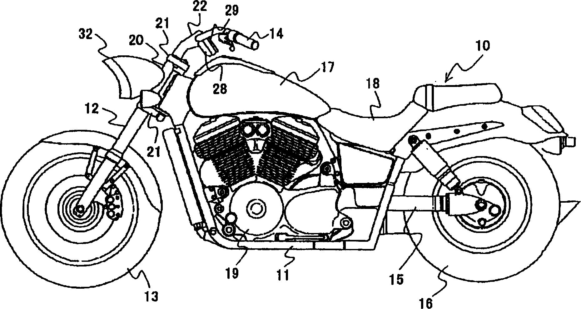
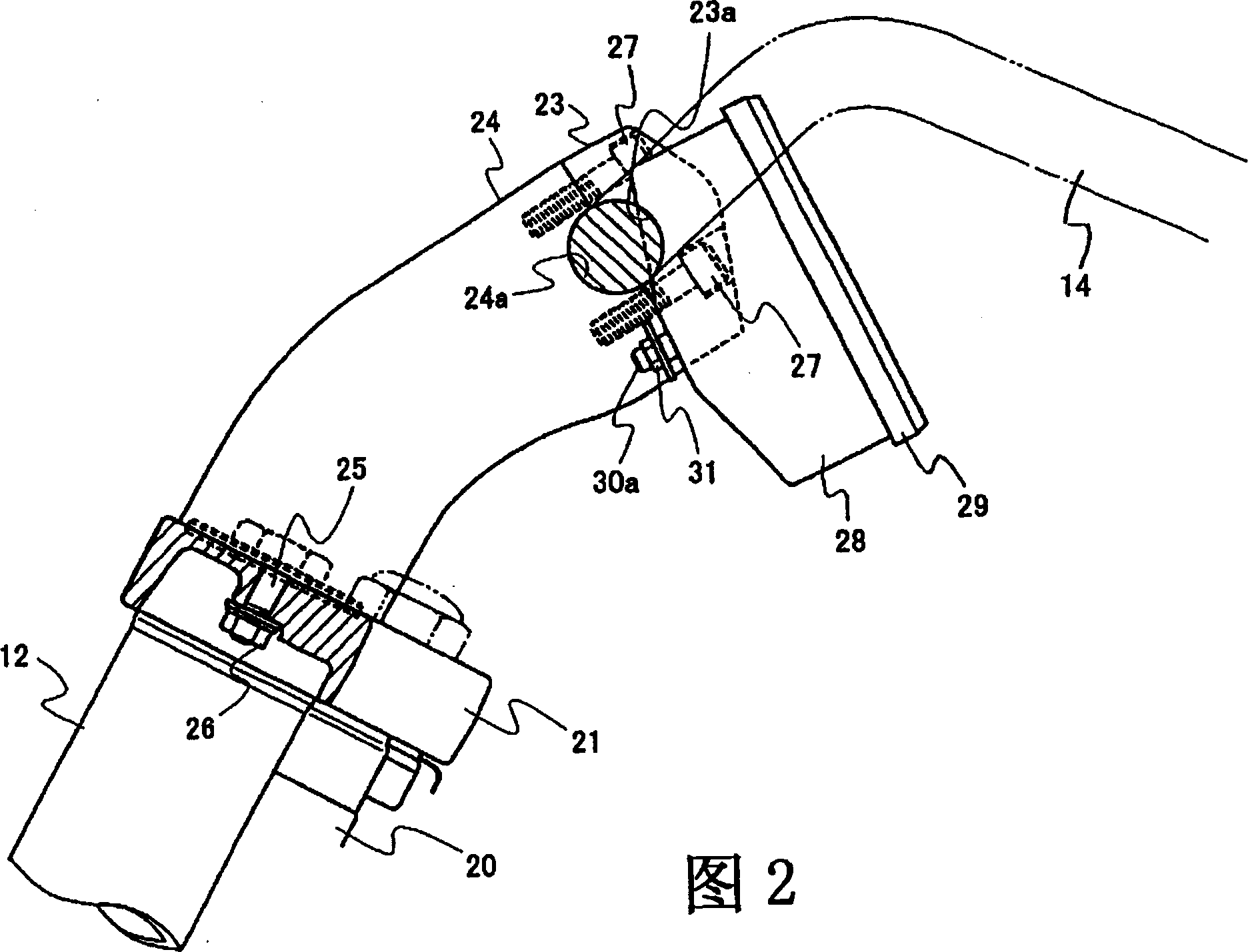
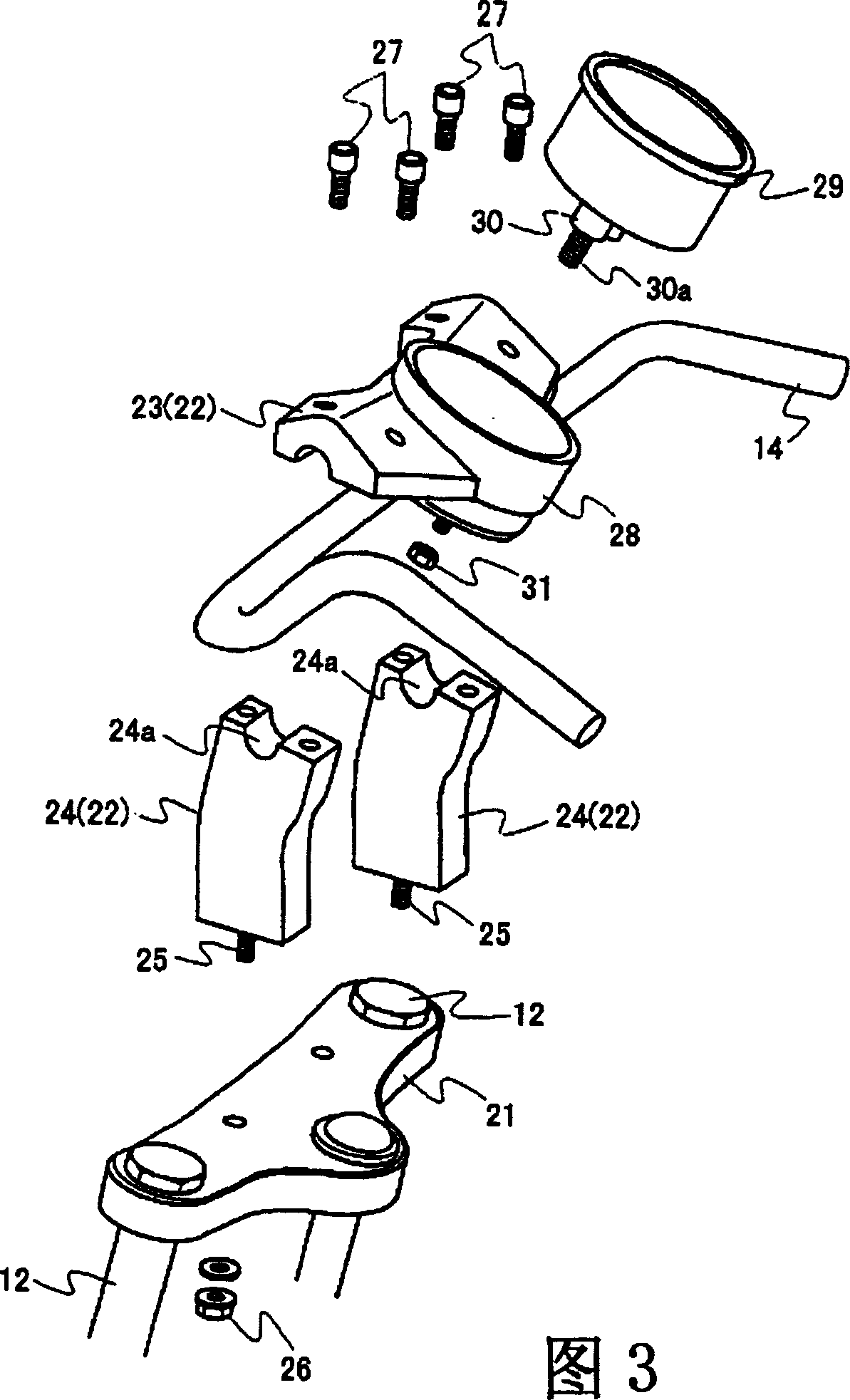
[0018] Hereinafter, one embodiment of the present invention will be described with reference to the drawings.

[0019] figure 1 Among them, the symbol 10 represents the automatic two-wheel vehicle applicable to this embodiment, and the automatic two-wheel vehicle 10 is roughly composed of the following: a vehicle frame 11, a front fork 12 mounted on the front part of the vehicle frame 11, rotatably mounted on The front wheel 13 at the lower end of the front fork 12 is installed on the steering handle 14 at the upper end of the front fork 12, and the rear fork 15 is rotatably installed at the bottom rear of the aforementioned vehicle frame 11. The rear wheel 16 at the rocking end of the rear fork 15 is mounted on the top of the vehicle frame 11, the fuel tank 17 at the rear position of the steering handle 14, the seat 18 at the rear position of the fuel tank 17, An engine 19 mounted below the aforementioned fuel tank 17 .

[0020] In more detail, the front fork 12 is disposed...


PUM


Abstract

The invention is to provide a structure for mounting a speedometer to a motorcycle enabling the speedometer to be mounted without impairing the design of the motorcycle. A fork support member 21 for supporting the front fork 12 of the motorcycle 10 is provided with a steering handle holder 22 for fixing a steering handle 14 and the speedometer 29 is mounted to the steering handle holder.

Description

technical field [0001] The present invention relates to an installation structure of an automatic motorcycle speedometer. Background technique [0002] A conventional mounting structure for an automatic motorcycle speedometer has been proposed, for example, in JP-A-11-208557. [0003] The structure of this technology is shown in a simplified figure 4. At the front of the fork support member 2 that rotatably connects the front fork 1 to the body frame (not shown), mounting parts such as clips are installed, and the speedometer 4 is fixed. on the mounting part 3. [0004] In the prior art, the following problems remain to be improved. [0005] Generally, a headlight is installed in front of the front fork 1, and the headlight greatly affects the design effect of the motorcycle. [0006] However, in the aforementioned installation structure, since the speedometer 4 is protrudingly fixed on the front of the front fork 1, the position of the speedometer is arranged near the to...

Claims


Application Information

Patent Timeline
Patent Type & Authority Patents(China)
IPC IPC(8): B62J11/00B62J99/00B62K23/00
CPCB62J99/00B62K23/00B62J11/00B62J2099/0033B62J50/225
Inventor 小仓秀夫山口靖二伊东理基须田敏彦
Owner HONDA MOTOR CO LTD
Learn More