Check patentability & draft patents in minutes with Patsnap Eureka AI!

Thermosensitive switch

A thermal induction and switching technology, applied in thermal switches, thermal switch components, electrical switches, etc., can solve problems such as deformation, adverse effects of temperature characteristics of bimetal 14, and increased thickness

Inactive Publication Date: 2005-07-06
ALPS ALPINE CO LTD
View PDF0 Cites 0 Cited by
  • Summary
  • Abstract
  • Description
  • Claims
  • Application Information

AI Technical Summary

Problems solved by technology

[0010] In the heat-sensitive switch structure in the prior art as described above, the connecting terminal portions 18 and 19, which are the other ends of the movable side terminal 15 and the fixed side terminal 12, are formed from the bimetal The fixed installation part on the piece 14 and the above-mentioned movable side terminal 15, or the fixed installation part on the above-mentioned fixed contact point 11 is directly led to the structure outside the above-mentioned housing 17, so for the above-mentioned connecting terminal part during installation When an external force is applied to 18 and 19, the above-mentioned connecting terminal parts 18 and 19 will be bent along the plate thickness direction, and the front end part of the above-mentioned movable contact point 13 fixedly installed on the above-mentioned bimetal 14 will be bent. position, and the position on the above-mentioned fixed contact point 11 is deformed, so there is a problem that it will adversely affect the temperature characteristics of the above-mentioned bimetallic strip 14
[0011] In addition, in the embedded portion of the movable side terminal 15, in order to suppress the influence of terminal bending, a multi-stage bent portion 15a is formed inside the above-mentioned housing 17, so there is a further increase in thickness due to this bent portion 15a. increase, making it difficult to miniaturize and reduce the thickness of the switch

Method used


Image

  • Thermosensitive switch
  • Thermosensitive switch
  • Thermosensitive switch

Examples


Embodiment Construction

[0033] Embodiments of the present invention will be described in detail below with reference to the accompanying drawings.

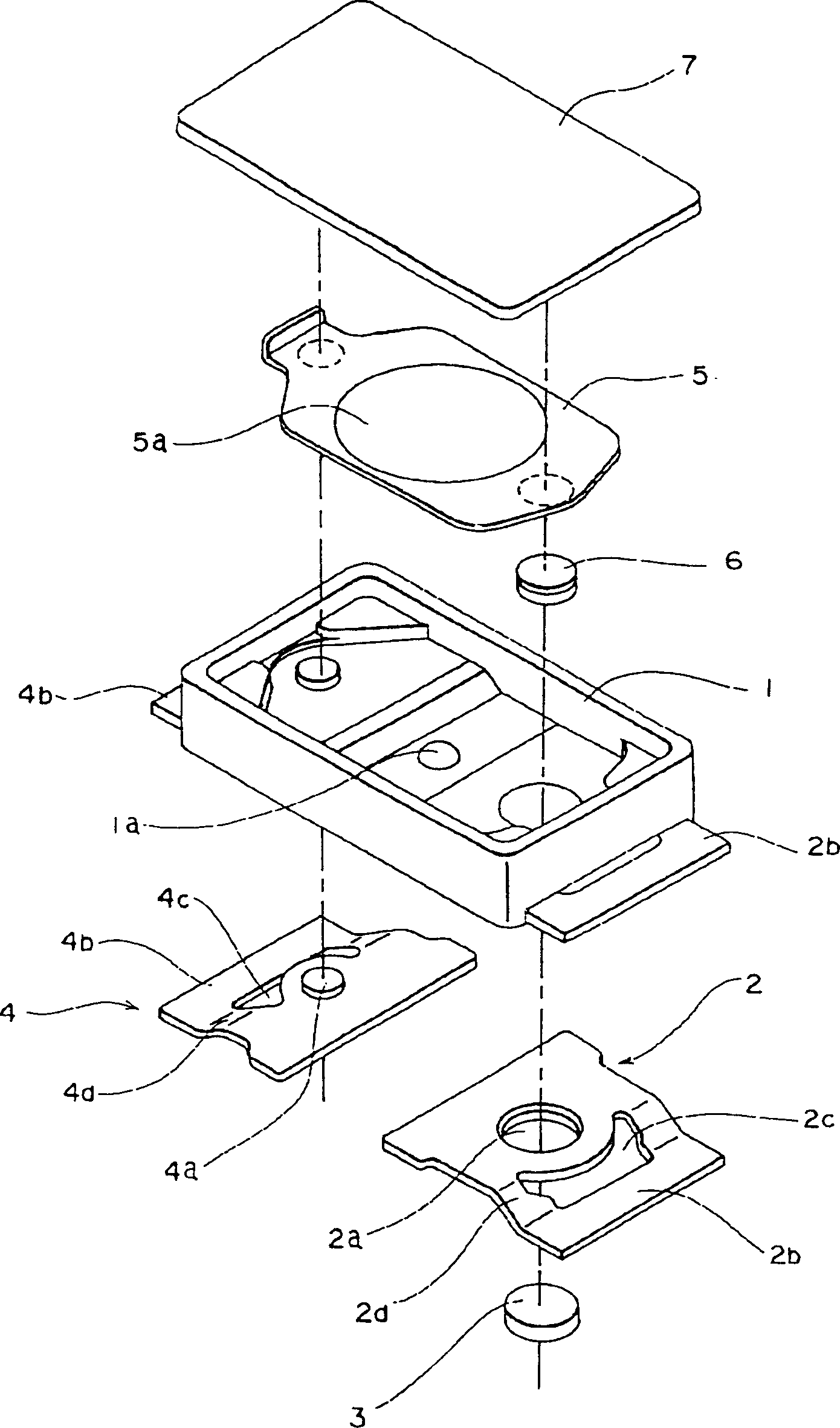
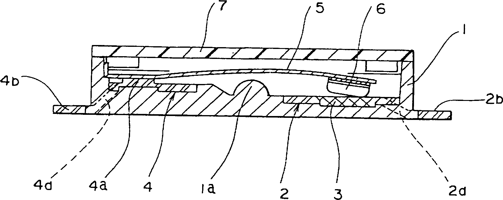
[0034] as Figure 1 to Figure 9 As shown, the insulating case 1 may be composed of an insulating material such as synthetic resin, and may be formed in a box shape with an open top. Various terminals as described later may also be arranged at the inner bottom of the insulating case 1 , and one end of each terminal is led out from the two side surfaces of the insulating case 1 to the outside. Further, at the central portion of the inner bottom surface of the above-mentioned insulating case 1, a supporting protrusion 1a protruding in a hemispherical shape from the inner bottom surface is provided.

[0035] The first terminal 2 may be made of a conductive metal material such as phosphor bronze, and may be formed in a flat plate shape. At one end of the first terminal 2, a mounting hole 2a is fixedly installed at the fixed contact point 3 made of silver tin ...


PUM


Abstract

PURPOSE: To provide a small-sized and thin-type thermally-actuated switch which allows relaxing effect of external stress upon a fixing part of each terminal to a bimetal piece or fixed contact even when external force is applied to the terminal led out of a case so as to reduce effect of displacement of the bimetal piece or fixed contact, and having a stable temperature characteristic. CONSTITUTION: This thermally-actuated switch has an insulation case 1; a first terminal 2 installed in the insulation case 1, fixedly attached with a fixed contact 3 on one side and led out of the insulation case 1 on the other side; a bimetal piece 5 fixedly attached with a moving contact 6 on one side, inverting according to a temperature to contact with and separate from the fixed contact 3; and a second terminal 4 installed in the insulation case 1, fixedly attached with the other side of the bimetal piece 5 on one side and led out of the insulation case 1 on the other side. Opening parts 2c, 4c are formed between the fixing part of the first terminal 2 to the fixed contact 3 and the other end side led out of the insulation case 1, and / or between the fixing part of the second terminal 4 to the bimetal piece 5 and the other end side led out of the insulation case 1.

Description

technical field [0001] The invention relates to a thermal induction switch, in particular to a switch structure capable of reversing a movable contact point through the thermal induction effect of a bimetal sheet, and further opening and closing an electrical contact point. Background technique [0002] The heat-sensitive switch has a heat-sensitive element (bimetallic sheet) formed by laminating several metal parts with different thermal expansion coefficients as a movable electrode of the movable piece, and together with the movable electrode forms a contact point. The fixed pole of the circuit in closed form, so that the electrical equipment can be protected by connecting this heat-sensitive type switch in the electrical equipment circuit. [0003] That is to say, when the thermal induction switch connected in the electrical equipment circuit has an excessive current flowing through the electrical equipment and the ambient temperature is too high, the contact point of the...

Claims


Application Information

Patent Timeline
Patent Type & Authority Patents(China)
IPC IPC(8): H01H37/54
CPCH01H37/5418
Inventor 大北正夫
Owner ALPS ALPINE CO LTD
Features
  • R&D
  • Intellectual Property
  • Life Sciences
  • Materials
  • Tech Scout
  • Unparalleled Data Quality
  • Higher Quality Content
  • 60% Fewer Hallucinations
Learn More