
Driving method of plasma display board

A driving method, plasma technology, applied to static indicators, instruments, etc., can solve the problem of unsatisfactory narrow pulse erasing effect, achieve improved display effect, increase display efficiency, and improve the effect of erasing waveform

Inactive Publication Date: 2005-08-24
SOUTHEAST UNIV
View PDF0 Cites 0 Cited by
  • Summary
  • Abstract
  • Description
  • Claims
  • Application Information

AI Technical Summary

Problems solved by technology

However, the erasing effect of a narrow pulse with a single pulse width is not ideal

Method used


Image

  • Driving method of plasma display board
  • Driving method of plasma display board
  • Driving method of plasma display board

Examples


specific Embodiment 2

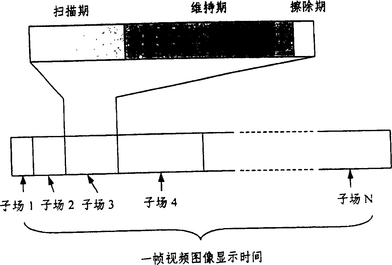
[0018] According to the above-mentioned embodiments 1 and 2, if the erasing period of each subfield is changed to 9 groups of positive and negative narrow erasing pulses issued continuously by the scanning electrodes, the pulse widths are 3 groups of 900 nanoseconds, 3 groups of 600 nanoseconds and 3 groups respectively. Group 300 nanoseconds, still keep the pulse width from large to small, the pulse amplitude is the same as the positive and negative pulse amplitude of the maintenance period, the addressing electrode remains grounded, and the grid plate electrode remains grounded or suspended, which constitutes the present invention. Specific embodiment 3.

[0019] According to the above-mentioned embodiments 1, 2 and 3, if the width of the erasing narrow pulse in each sub-field erasing period is changed to be different from the width of the sustain pulse, specifically 80% of the width of the sustain pulse, this constitutes a specific embodiment of the present invention 4.


PUM


Abstract

A drive method for the electrically conductive grid mesh plate type plasma display panel to display video images with grayscales includes driving various basic working waveforms such as scanning waveform, holding waveform and erasing waveform, especially the improved effective erasing waveform. Its advantages are higher display effect and improved grayscale feeling.

Description

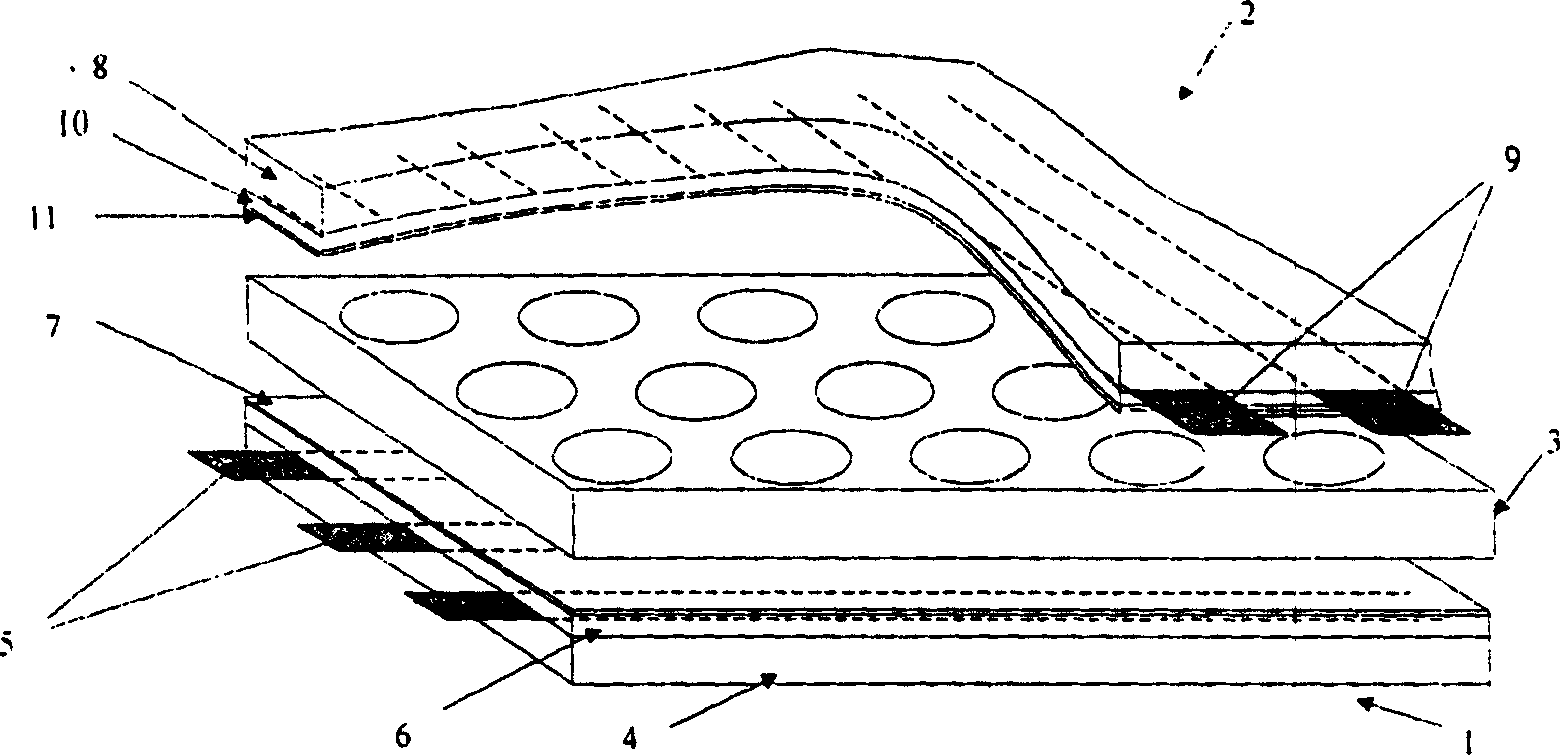
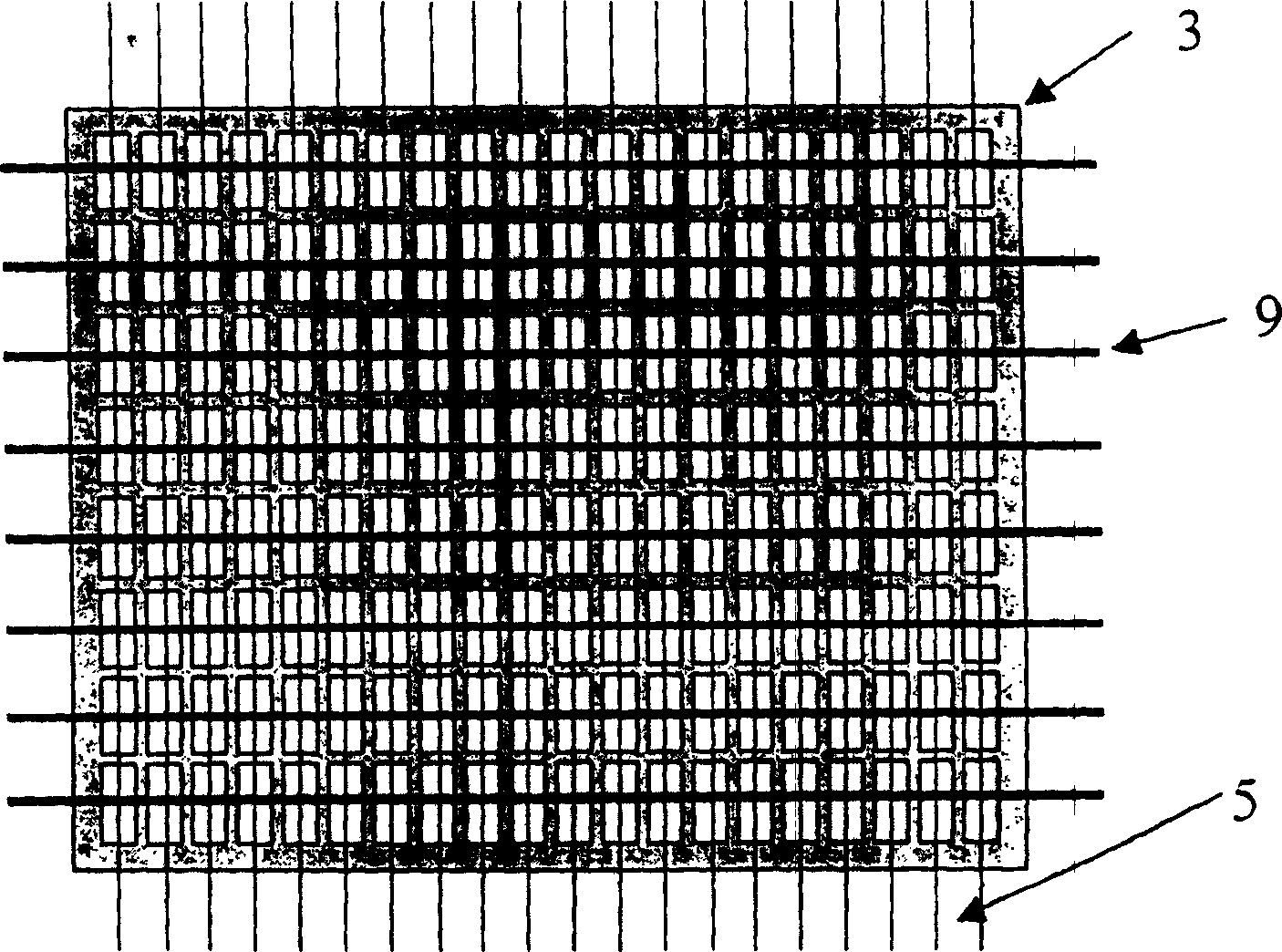
(1) Technical field [0001] The invention belongs to the field of plasma display technology, and in particular relates to a full-color dynamic image display driving method with gray levels applied to a conductive grid-type plasma display panel, in particular to improving erasing performance by combining narrow pulses with gradually changing widths , to improve the image display quality of the conductive grid panel type plasma display panel. (2) Background of the invention [0002] Such as figure 1 As shown, the structure of the conductive grid plate type plasma display panel is mainly composed of a rear substrate 1 , a grid plate 3 and a front substrate 2 . Rear substrate 1 comprises rear substrate glass substrate 4, the first electrode 5 (addressing electrode) formed on rear substrate glass substrate 4, the dielectric layer 6 formed on rear substrate glass substrate 4, on dielectric layer 6 The protective film 7 that forms; Front substrate 2 comprises front substrate glass...

Claims


Application Information

Patent Timeline
Patent Type & Authority Patents(China)
IPC IPC(8): G09G3/288
Inventor 汤勇明郑姚生夏军张雄
Owner SOUTHEAST UNIV
Learn More