A laser animation display method

A display method and laser technology, applied in optics, instruments, projection devices, etc., can solve problems such as unsatisfactory effects

Active Publication Date: 2018-12-18
BEIJING CENT PRESS UNION TECH +1
View PDF6 Cites 2 Cited by
  • Summary
  • Abstract
  • Description
  • Claims
  • Application Information

AI Technical Summary

Problems solved by technology

[0004] The current mainstream laser light products are still based on static images or combinations of static images that h...

Method used


Image

  • A laser animation display method
  • A laser animation display method
  • A laser animation display method

Examples


Embodiment 1

[0071] This embodiment provides a method for displaying laser animation. The display system includes three parts: a laser source, a diffractive optical element, and a mechanical drive device, wherein the diffractive optical element is arranged on the mechanical drive device, and multiple A microstructure with associated pattern phase information, each microstructure corresponds to a different frame of image, driven by a mechanical drive device to make the diffractive optical element perform relative translational movement with respect to the laser beam emitted by the laser light source; the mechanical The driving device is a linear driving device.

[0072] The display method of laser animation comprises the following steps:

[0073] S1: First, the laser is emitted by the laser source, and the laser is incident on the first microstructure pattern on the diffractive optical element placed on the plane perpendicular to the laser propagation direction, thereby carrying the phase i...

Embodiment 2

[0086] A display method of laser animation in this embodiment, the display system includes three parts: a laser source, a diffractive optical element and a mechanical drive device, wherein the diffractive optical element is arranged on the mechanical drive device, and a plurality of diffractive optical elements are arranged on the The microstructure of the associated pattern phase information, each microstructure corresponds to a different frame of image, and the diffractive optical element is driven by the mechanical drive device to perform relative translational movement relative to the laser beam emitted by the laser light source; the mechanical drive The device is a non-gear type in the peripheral drive device.

[0087] The display method of laser animation comprises the following steps:

[0088] S1: First, the laser source emits laser light with a propagation direction parallel to the horizontal plane, and the laser light is incident on the first microstructure pattern on...
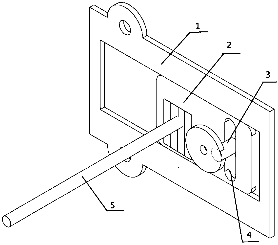
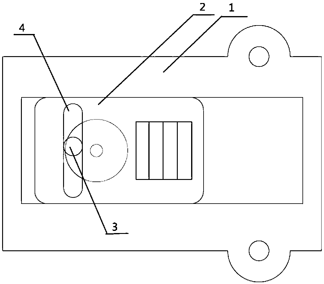
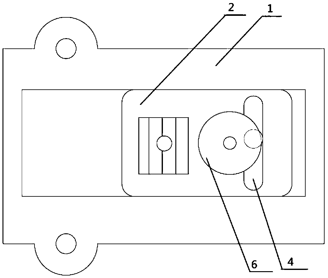
Embodiment 3

[0100] This embodiment provides a method for displaying laser animation. The display system includes three parts: a laser source, a diffractive optical element, and a mechanical drive device, wherein the diffractive optical element is arranged on the mechanical drive device, and multiple A microstructure with associated pattern phase information, each microstructure corresponds to a different frame of image, driven by a mechanical drive device to make the diffractive optical element perform relative translational movement with respect to the laser beam emitted by the laser light source; the mechanical The driving device is a gear type in a circular driving device.

[0101] The display method of laser animation comprises the following steps:

[0102] S1: First, the laser source emits laser light with a propagation direction parallel to the horizontal plane, and the laser light is incident on the first microstructure pattern on the diffractive optical element placed perpendicula...


PUM


Abstract

The invention discloses a laser animation display method. The display system comprises a laser source, a diffractive optical element and a mechanical driving device. The display method comprises the following steps: S1, first a laser beam whose propagation direction is parallel to a horizontal plane is emitted from the laser source, and the laser beam is incident on a pattern of a first microstructure on the diffractive optical element; S2, the diffractive optical element is driven to be translate by a mechanical driving device so that a laser beam is irradiated on a pattern of a second microstructure of the diffractive optical element, and the patterns on other microstructures on the diffractive optical element are irradiate by the laser beam in turn according to the method; and S3, Continuously moving in cycles to create an animation effect on the terminal screen. The invention realizes the organic combination of the diffractive optical element and the driving device, and realizes the laser animation display on the premise that the motion control unit is not additionally added and the system volume and the cost are hardly increased. The method is low in cost, and easy to popularize.

Description

technical field [0001] The invention relates to an animation display method, in particular to a laser animation display method. Background technique [0002] The laser lamp is mainly composed of three parts: laser light source, mechanical movement device and diffractive optical element. The surface of the diffractive optical element is processed with micro-nano-scale steps. Using the diffraction effect of the steps on light, the diffractive optical element can output the incident point-shaped laser as the required image. Due to the high brightness and high collimation characteristics of the laser, the laser light can realize long-distance and high-brightness image display, so it has developed rapidly in the European, American and domestic markets in recent years. [0003] Although laser lights have a history of more than 10 years, most laser light products on the market can only display static images. In order to enrich the performance content and improve the performance e...

Claims


Application Information

Patent Timeline
IPC IPC(8): G03B21/20G03B21/14
CPCG03B21/142G03B21/2033
Inventor 丛森钟良王豪马平平
Owner BEIJING CENT PRESS UNION TECH
Why Eureka
Try Eureka