Multi-unit air conditioner and control method

An air conditioner and multi-unit technology, which is applied in the direction of air conditioning system, machine operation mode, heating and ventilation control system, etc., can solve the problems that multi-unit air conditioners cannot properly meet the requirements and restrictions

Inactive Publication Date: 2005-12-21
LG ELECTRONICS INC
View PDF0 Cites 2 Cited by
  • Summary
  • Abstract
  • Description
  • Claims
  • Application Information

AI Technical Summary

Problems solved by technology

[0004] However, even if some rooms require heating and other rooms require cooling in the divided space, the multi-unit air conditioner can only operate in a uniform cooling mode or heating mode, and the multi-unit air conditioner suffers from the aspect of not being able to properly meet the requirements. limit
[0005] For example, even in buildings where the temperature of the rooms varies by location or time of day, rooms on the north side of the building require heating, and rooms on the south side of the building are exposed to the sun and require cooling. Multi-unit air conditioners that operate in single mode are out of the question
[0006] In addition, buildings equipped with computer rooms require cooling not only in summer but also in winter to solve the heat load problem of computer-related equipment, and the prior art multi-unit air conditioners cannot adequately address this requirement

Method used


Image

  • Multi-unit air conditioner and control method
  • Multi-unit air conditioner and control method
  • Multi-unit air conditioner and control method

Examples


Embodiment Construction

[0038] Reference will now be made in detail to the preferred embodiments of the present invention, examples of which are illustrated in the accompanying drawings. When describing the embodiments of the present invention, the same parts are given the same names and reference numerals, and will not be described again.

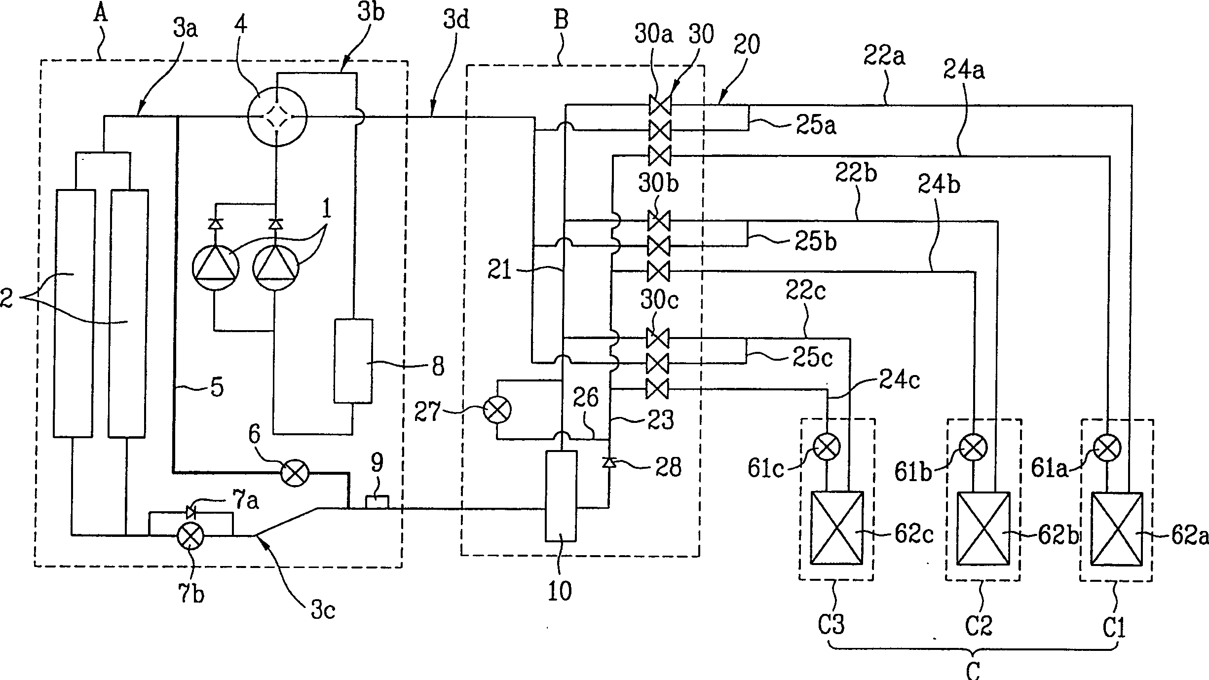
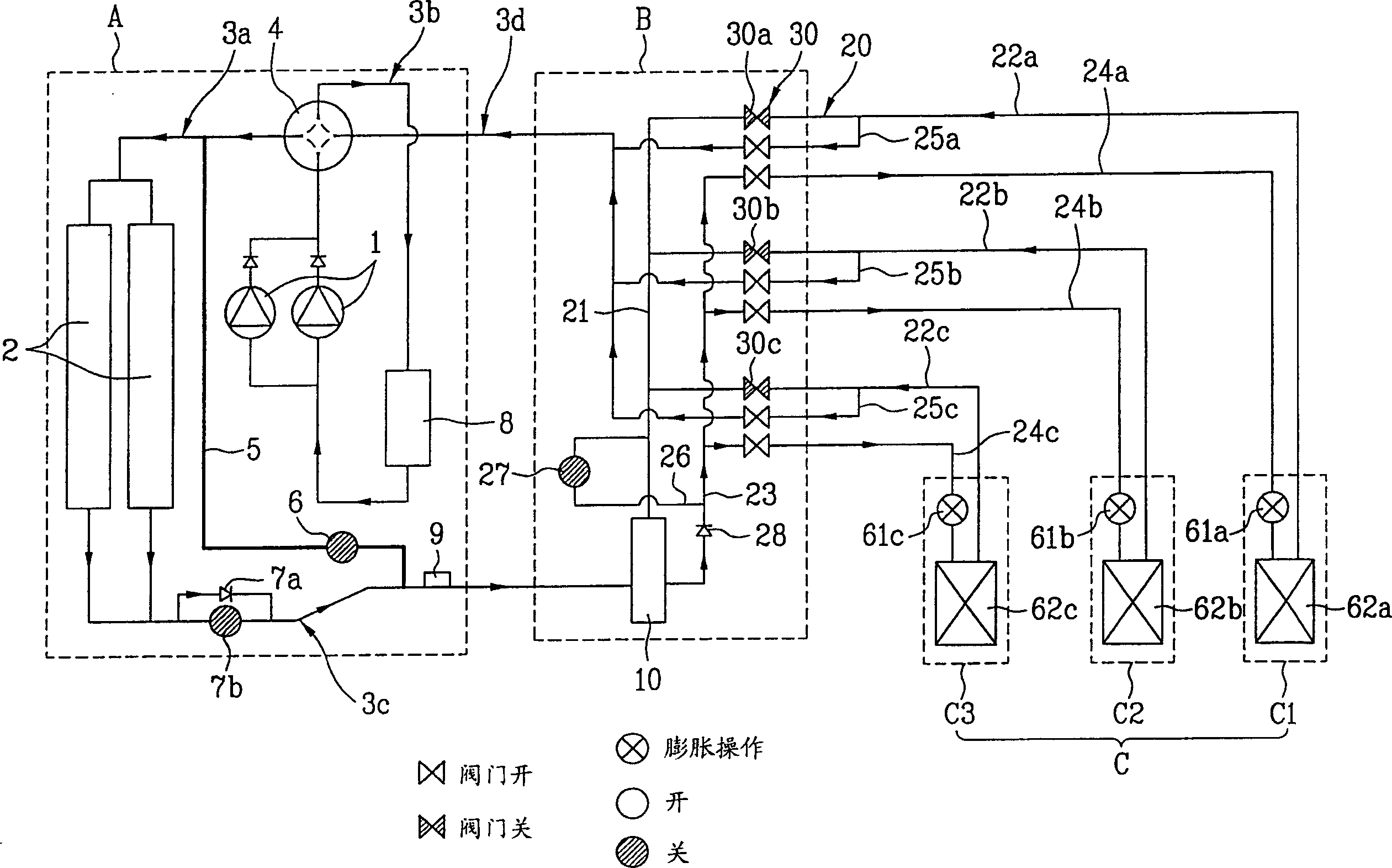
[0039] refer to figure 1 , The air conditioner according to the preferred embodiment of the present invention includes an outdoor unit 'A', a distributor 'B' and a plurality of indoor units 'C', namely 'C1, 'C2' and 'C3'. The outdoor unit 'A' has a compressor 1 and an outdoor heat exchanger 2, and the distributor 'B' has a gas-liquid separator 10 and a distribution piping system 20. Each of the indoor units 'C', namely 'C1', 'C2' and 'C3' has an indoor heat exchanger 62 and an indoor electronic expansion valve 61.

[0040] The air conditioner has a system in which, according to a first operation mode for cooling all rooms, a second operation mode for heating all ...


PUM


Abstract

A multi-unit air conditioner includes: an outdoor unit including a flow path control valve for controlling the flow path of refrigerant from a compressor, an outdoor heat exchanger one side of which communicates with the flow path control valve, a first side One end of the first bypass line is connected to the first line connecting the flow path control valve and the outdoor heat exchanger, and the other end is connected to the second line connected to the other end of the outdoor heat exchanger. a control valve provided on the first bypass line for controlling the flow rate of refrigerant passing through the first bypass line; an indoor unit having an indoor heat exchanger and an indoor electronic expansion valve installed in each room; a distributor, for selectively distributing refrigerant received through one of the two lines connected to the outdoor unit to the indoor unit and returning the refrigerant to the outdoor unit through the other line; and a control device for measuring the The gas / liquid mixing ratio of the refrigerant in the refrigerant is combined after passing through the first bypass line and the outdoor heat exchanger respectively. The control device is used to control the opening of the flow control valve, thereby controlling the mixing ratio.

Description

[0001] This application claims priority from Korean Application No. P2002-32901 filed on Jun. 12, 2002, the contents of which are incorporated herein by reference. technical field [0002] The invention relates to a multi-unit air conditioner, in particular to a multi-unit air conditioner with an improved outdoor piping system and a refrigerant mixing ratio control system and a control method thereof. Background technique [0003] Generally, an air conditioner is a device used to cool or heat spaces, such as living spaces, restaurants, and offices. Currently, in order to efficiently cool or heat a space divided into a plurality of rooms, multi-unit air conditioners have been continuously developed. A multi-unit air conditioner typically has an outdoor unit and multiple indoor units, each of which is connected to the outdoor unit and installed indoors to cool or heat the room, operating in one of cooling or heating modes . [0004] However, even if some rooms require heatin...

Claims


Application Information

Patent Timeline
Patent Type & Authority Patents(China)
IPC IPC(8): F24F11/02F24F11/00F25B1/00F25B13/00F25B29/00F25B41/00
CPCF25B13/00F25B2313/006F25B2313/0231F25B2313/0252F25B2313/0253F25B2400/075F24F1/00
Inventor 黄一男
Owner LG ELECTRONICS INC
Why Eureka
Try Eureka