Supercharge Your Innovation With Domain-Expert AI Agents!

Liquid sprayers

A sprayer and liquid technology, applied in the direction of liquid injection devices, injection devices, injection devices, etc., can solve the problems of inability to generate high-speed gas-droplet jets, and achieve the effects of improving fire extinguishing efficiency, reducing energy consumption, and improving utilization efficiency

Inactive Publication Date: 2006-01-18
安德烈·L·杜什金 +1
View PDF0 Cites 0 Cited by
  • Summary
  • Abstract
  • Description
  • Claims
  • Application Information

AI Technical Summary

Problems solved by technology

However, the given examples are not capable of producing high-velocity, finely dispersed gas-droplet jets

Method used


Image

  • Liquid sprayers
  • Liquid sprayers
  • Liquid sprayers

Examples


Embodiment Construction

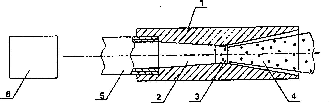
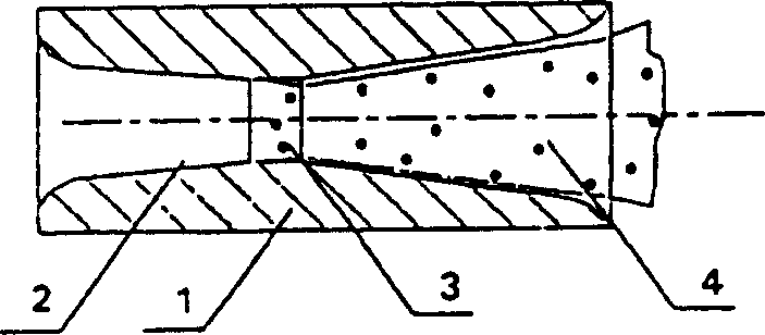
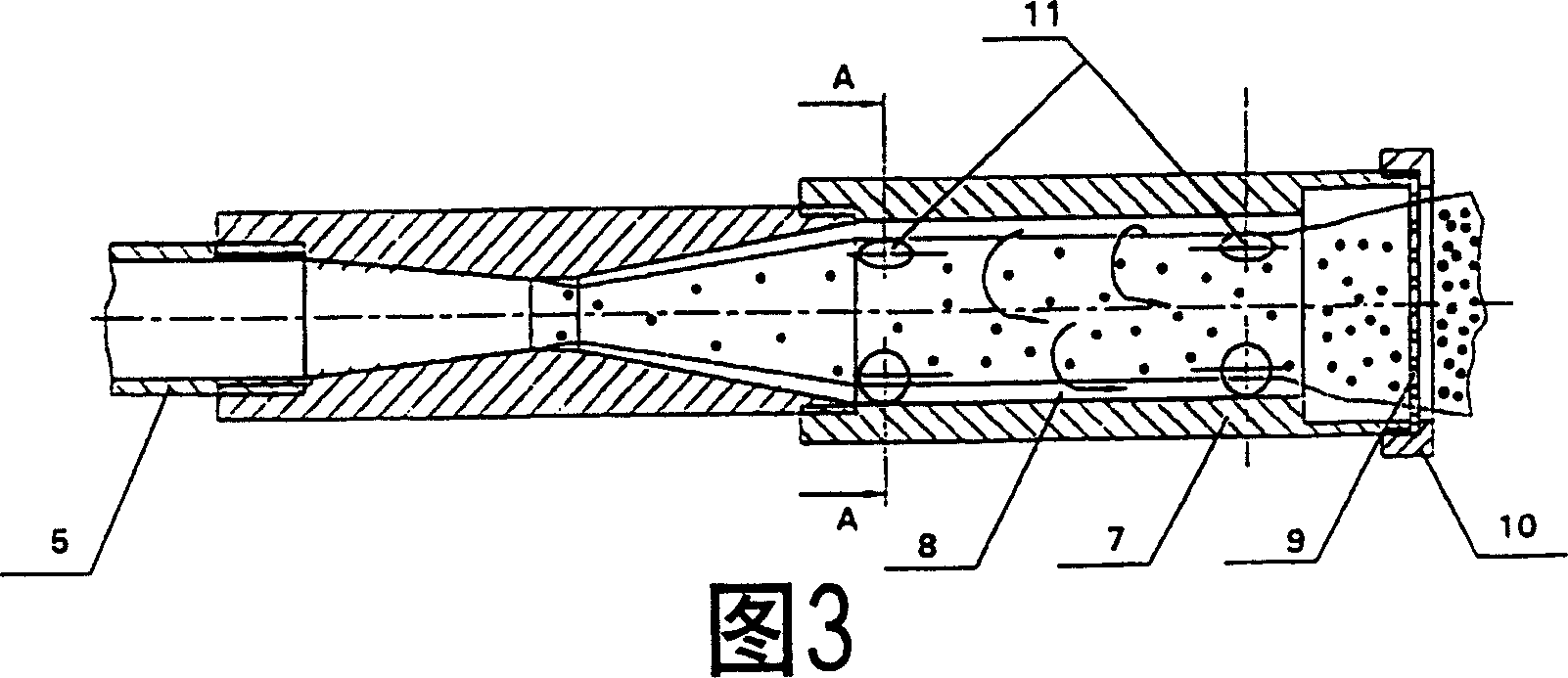
[0036] The liquid sprayer that forms according to first embodiment of the present invention (referring to Figures 1 to 5 ) comprises a housing 1 with a flow channel formed by interconnecting axially aligned parts. An inlet part 2 is made in the form of a shrink tube having an outlet connected to the inlet of the cylindrical part 3 . An outlet section 4 made in the form of a conical diffuser comprises an inlet connected to an outlet of the cylindrical section 3 . The length of the cylindrical portion is 0.7 times its diameter. One cone defining the shrink tube had an apex angle of 13° and one cone defining the diffuser had an apex angle of 20°.

[0037] The housing 1 is connected on the inlet side of the shrink tube to a pipe connection 5 of the line of a liquid supply system. The liquid supply system includes a pump or pressure type liquid booster 6 .

[0038] In a preferred embodiment (see figure 2 ), the inlet edge of the constriction tube that determines the flow cha...


PUM


Abstract

A liquid sprayer according to the first embodiment of the invention comprises a casing (1) having a flow-through channel composed of sequentially joined inlet portion (2) formed as a converging tube, a cylindrical portion (3) and an outlet portion (4) formed as a conical diffuser. A length of cylindrical portion (3) is not less than a radius thereof. A cone angle of the diffuser forming the outlet portion (4) of the flow-through channel is greater than a cone angle of the converging tube forming the inlet portion (2) of the same channel. According to the second embodiment of the invention, the converging tube forming the inlet portion of the flow-through channel is made conoid-shaped. Implementation of the invention allows steady-state fine-dispersed liquid flow to be generated at the minimal energy consumption.

Description

technical field [0001] The present invention relates to a liquid spray technology and can be used in fire protection systems, as part of treatment equipment, for fuel combustion in heating works and transport, as well as for environmental humidification and for spraying disinfectants and insecticides. Background technique [0002] Currently, various types of liquid sprayers are used in a variety of different fields, including fire fighting equipment, such as fire extinguishing sprayers. [0003] For example, US Patent No. 5,125,582 (IPC B05B1 / 00, published June 30, 1992) discloses the structure of a liquid sprayer designed to generate a cavitation flow. This prior art includes a housing with flow channels formed by nozzles and a cylindrical chamber. The nozzle is manufactured in the form of a shrinking tube communicating with a conical diffuser, the surfaces of which are not continuously joined. By supplying liquid under pressure into the inlet of the nozzle constriction t...

Claims


Application Information

Patent Timeline
Patent Type & Authority Patents(China)
IPC IPC(8): B05B7/10B05B1/00B05B7/00A62C31/02B05B1/34B05B7/04
CPCA62C31/02B05B7/0062B05B7/0425B05B7/0475B05B7/10B05B1/34B05B1/3402B05B7/04
Inventor 安德烈·L·杜什金亚历山大·V·卡尔佩谢乌
Owner 安德烈·L·杜什金
Features
  • R&D
  • Intellectual Property
  • Life Sciences
  • Materials
  • Tech Scout
  • Unparalleled Data Quality
  • Higher Quality Content
  • 60% Fewer Hallucinations
Learn More