C-type open MRI panel radio-frequency coil

A technology of radio frequency coil and magnetic resonance, which is applied in the field of C-shaped open magnetic resonance imaging flat radio frequency coil, which can solve the problems of difficult adjustment, complex structure, and reduced coil efficiency.

Inactive Publication Date: 2006-06-07
INST OF ELECTRICAL ENG CHINESE ACAD OF SCI
View PDF1 Cites 0 Cited by
  • Summary
  • Abstract
  • Description
  • Claims
  • Application Information

AI Technical Summary

Problems solved by technology

In this kind of circuit, it is necessary to distribute the current of the two coil plates at the RF input interface, and to tune the two coils separately. influence each other, making it difficult to adjust
[0005] Using the shielding layer as the current path solves the problem of the current loop, but the current of the shielding layer has a certain offset effect on the radio frequency field, which reduces the efficiency of the coil

Method used


Image

  • C-type open MRI panel radio-frequency coil
  • C-type open MRI panel radio-frequency coil
  • C-type open MRI panel radio-frequency coil

Examples


Embodiment Construction

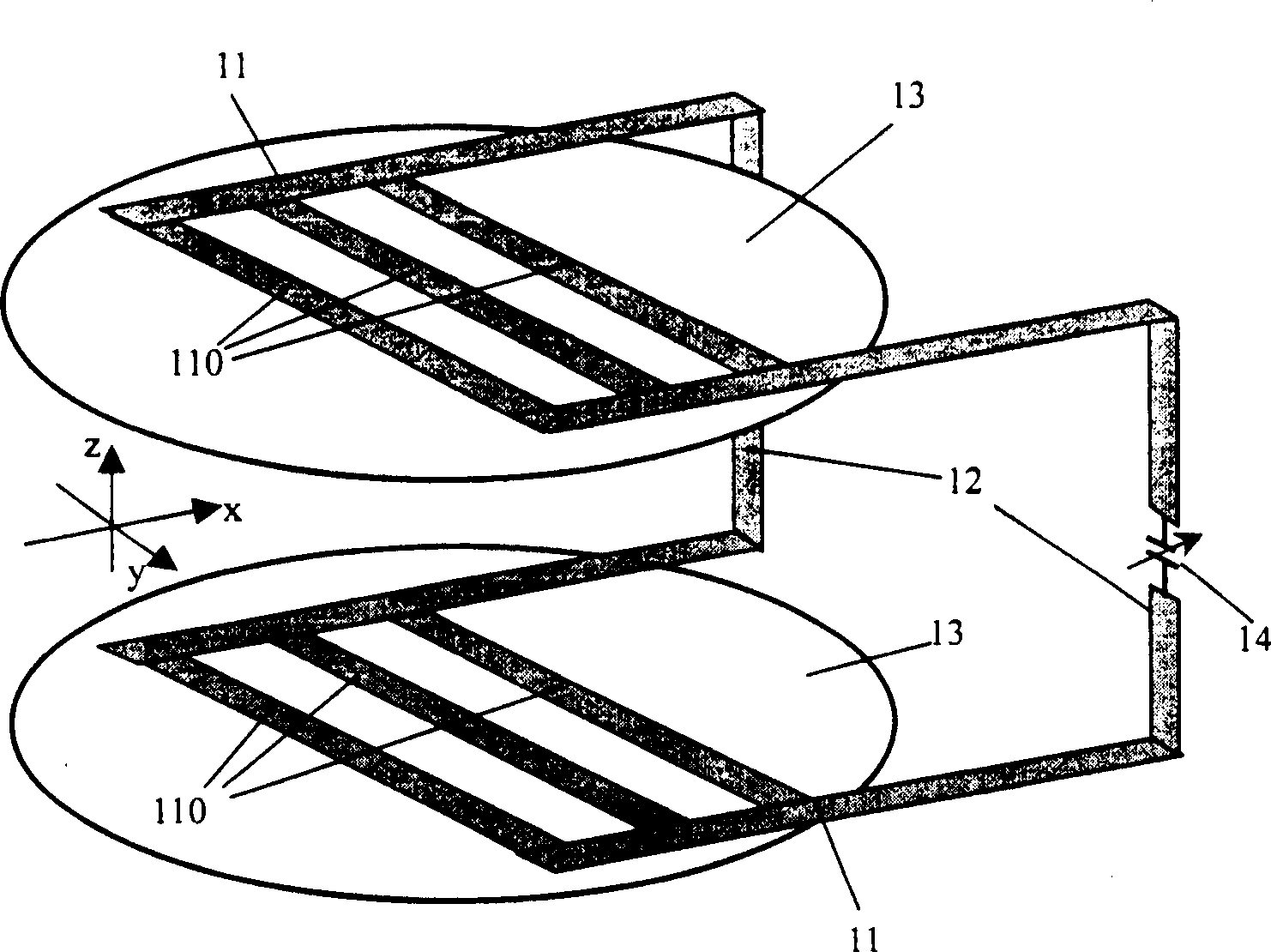
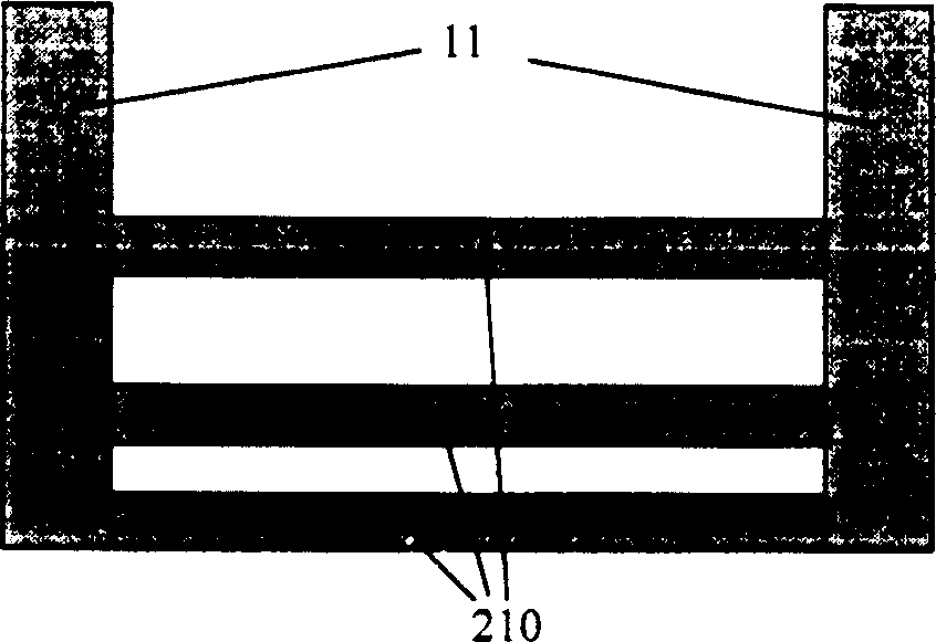
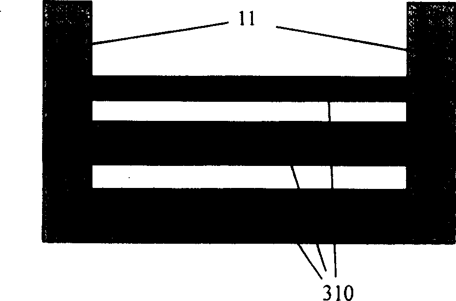
[0061] like figure 1 As shown, each of the upper and lower planar coils 13 has a set of coil conductor groups 110, and the two ends of the coil conductor groups 110 are connected to the two common connecting conductors 11 in the planar coil, wherein the common connecting conductors 11 extend out of the planar coil in the direction of the magnet vertical yoke 13, and is connected with two common connecting conductors 12 located in the vertical direction with the coil, thereby forming a closed loop. Obviously, the direction of the field generated by the coil conductors in the imaging area is the X direction, and the directions of the fields generated by the upper and lower coil conductors 110 in the imaging area are the same. A capacitor 14 is provided in a vertical common connecting conductor for adjusting the resonant frequency of the coil, and thus connected with the radio frequency input interface. It can be seen that the upper and lower flat RF coil wires at this time con...


PUM


Abstract

The invention discloses a flat radio frequency coil for magnetic resonance imaging. It is used to establish a radio frequency field between two magnetic pole surfaces of a magnet in a C-type open magnetic resonance system. The coil consists of two planar coils respectively fixed on the upper and lower magnetic pole surfaces. Each coil is equipped with a conductor group composed of multiple coil conductor elements arranged in parallel. Both ends of the conductor group are provided with common connecting conductors. The coil conductors The elements extend from the common connecting conductor on one side of the planar coil to the common connecting conductor on the other side, and the coil conductor elements and the common connecting conductor constitute the coil plane. The common connection conductors on the upper and lower planar coils are connected as a whole with the other two vertical common connection conductors placed on the outer sides of the planar coil; the vertical common connection conductors on either side are connected to the radio frequency interface, so that the upper and lower Two planar coils form a single RF coil.

Description

technical field [0001] The invention relates to a magnetic resonance imaging (MRI) system, in particular to a C-shaped open magnetic resonance imaging flat radio frequency coil. Background technique [0002] When the magnetic resonance imaging system works, the human body is placed in a strong static magnetic field, and the atomic nuclei in some areas of the human body are excited by sending radio frequency pulses to the human body. After the radio frequency field is removed, these excited nuclei radiate radio frequency signals, which are received by the antenna. Since the gradient magnetic field is added in this process, the spatial distribution information of the human body can be obtained through the radio frequency signal, thereby reconstructing a two-dimensional or three-dimensional image of the human body. [0003] The radio frequency coil is used to establish the radio frequency field and receive the radio frequency signal. A single radio frequency coil can be used f...

Claims


Application Information

Patent Timeline
Patent Type & Authority Patents(China)
IPC IPC(8): G01R33/341
Inventor 杨文晖宋涛王慧贤
Owner INST OF ELECTRICAL ENG CHINESE ACAD OF SCI
Why Eureka
Try Eureka