
Garbage furnace

A waste incinerator and grate technology, applied in the direction of incinerators, combustion methods, combustion types, etc., can solve problems such as insufficient waste incineration, reduced waste incineration efficiency, waste burning dead corners, etc., and achieve the effect of full combustion

Inactive Publication Date: 2006-08-02
周雪松
View PDF0 Cites 0 Cited by
  • Summary
  • Abstract
  • Description
  • Claims
  • Application Information

AI Technical Summary

Problems solved by technology

[0002] The garbage incinerator used in the prior art includes a furnace body, a material inlet, a movable material door, a fire grate, a slag outlet, a furnace, a push plate, and an air supply system. The rear half of the fire grate is provided with an auxiliary air duct , the air supply system includes a fan and a main air duct. The outlet of the main air duct is located on the side of the hearth in front of the furnace body. When the garbage is in the front half of the grate, it is only supplied with air through the main air duct for combustion, which often leads to insufficient air supply for garbage combustion. And it is easy to cause dead corners of garbage burning, resulting in insufficient burning of garbage. In addition, the burning garbage can only extend from one side of the furnace to the middle of the furnace and the other side. When new garbage is added by using the push plate, it is easy to break the outlet of the main air duct and burn. Garbage that burns easily will be turned off and cannot be continuously burned. If you want to continue burning the garbage in the garbage incinerator, you need to remove the garbage and re-ignite, which wastes manpower and reduces the efficiency of garbage incineration.

Method used


Image

  • Garbage furnace
  • Garbage furnace
  • Garbage furnace

Examples


Embodiment Construction

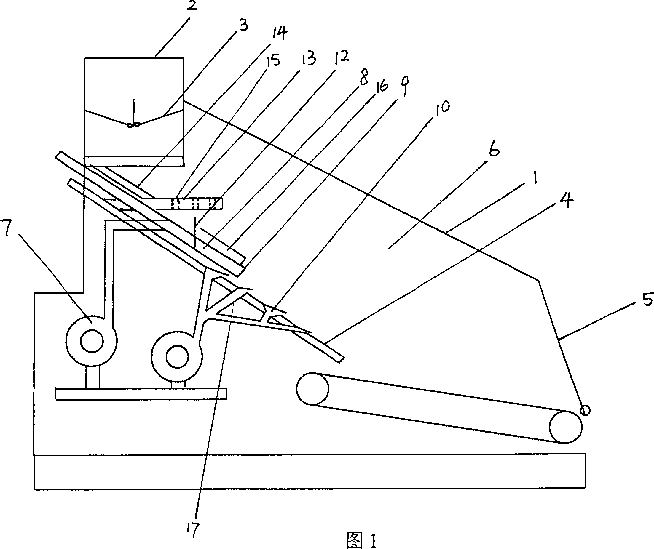
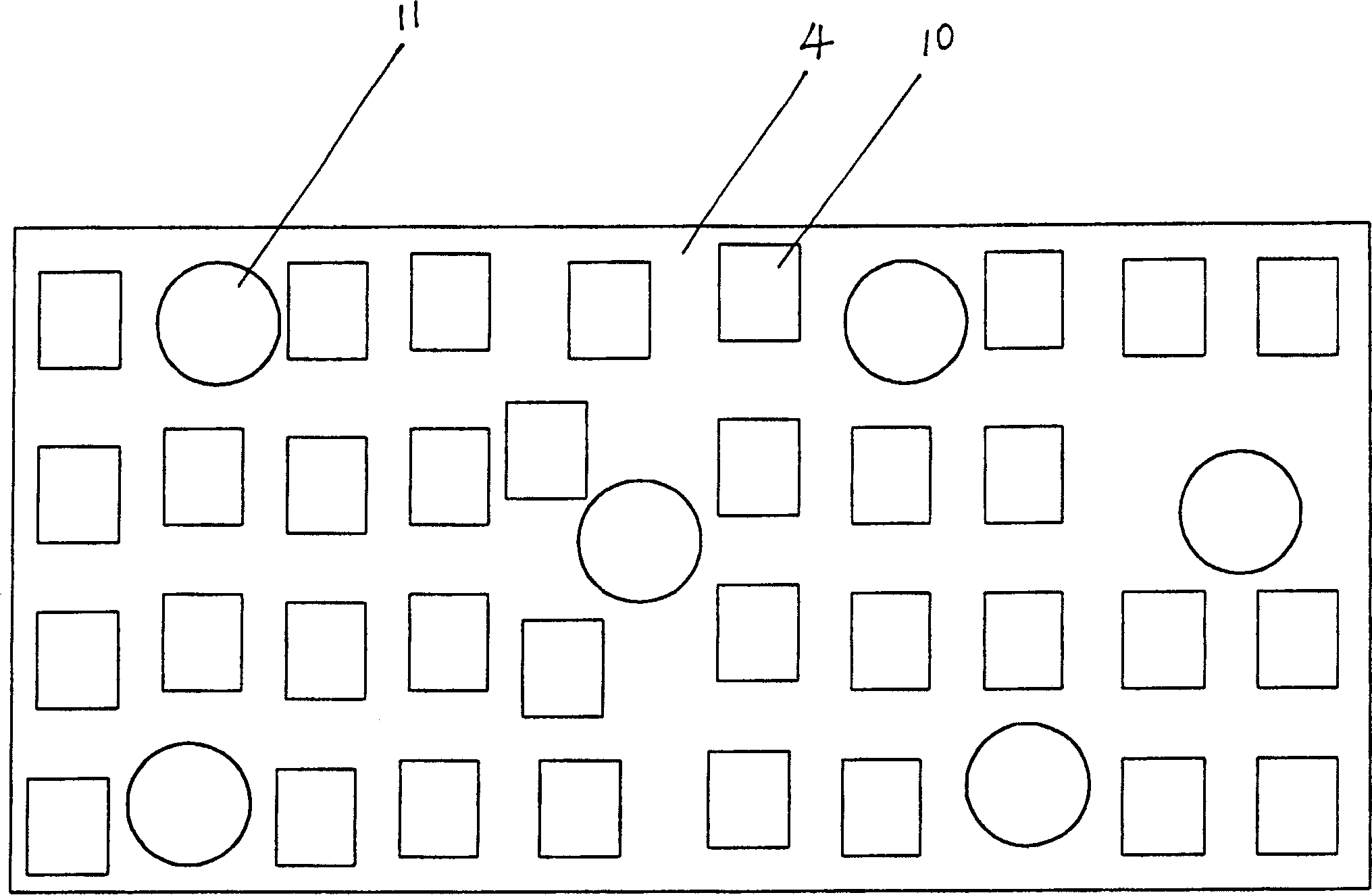
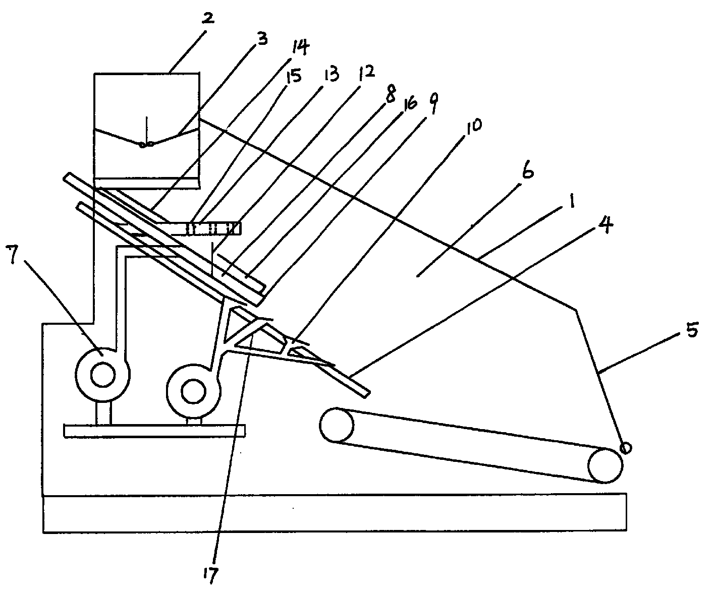
[0017] Figure 1, figure 2 As shown, the garbage incinerator of the present invention includes a body of furnace 1, a feed inlet 2, a movable material door 3, a fire grate 4, a slag outlet 5, a furnace 6, a push plate 12, an air supply system, and the air supply system includes a blower fan 7 and the main air duct 8, which is characterized in that: the main air duct 8 is arranged along the fire grate 4, its outlet 9 is located above the middle of the fire grate 4, and the fire grate 4 is provided with auxiliary air ducts 10 all over.

[0018] The fire grate 4 is a chain-type fire grate, and the auxiliary air duct 10 is a plurality of through holes arranged on the chain-type fire grate or is designed as a duckbill air duct (that is, a through-hole air duct) in order to prevent the auxiliary air duct from being blocked by garbage. raised).

[0019] The fire grate 4 can also be adopted as a plate fire grate, and the auxiliary air duct 10 is a plurality of through holes or duckbil...


PUM


Abstract

A garbage furnace is composed of main body, feed opening, movable gate, grate with auxiliary air channel, cinder discharging outlet, combustion box, push plate for moving garbage in the combustion box, and air supply system. Said air supply system consists of blower and air supplying trank arranged along grate. Its advantage is supplying air in different directions to eliminate dead angle and preventing fire extinguishing.

Description

technical field [0001] The invention relates to a municipal solid waste incinerator. Background technique [0002] The garbage incinerator used in the prior art includes a furnace body, a material inlet, a movable material door, a fire grate, a slag outlet, a furnace, a push plate, and an air supply system. The rear half of the fire grate is provided with an auxiliary air duct , the air supply system includes a fan and a main air duct. The outlet of the main air duct is located on the side of the hearth in front of the furnace body. When the garbage is in the front half of the grate, it is only supplied with air through the main air duct for combustion, which often leads to insufficient air supply for garbage combustion. And it is easy to cause dead corners of garbage burning, resulting in insufficient burning of garbage. In addition, the burning garbage can only extend from one side of the furnace to the middle of the furnace and the other side. When new garbage is added by...

Claims


Application Information

Patent Timeline
IPC IPC(8): F23G5/00F23G5/26
Inventor 周广胜周雪松
Owner 周雪松
Learn More