
Push-button switch

A button and switch technology, applied in the direction of electric switches, electrical components, circuits, etc., can solve the problem of noisy reset sound

Inactive Publication Date: 2007-01-17
MIYAMA ELECTRIC CO LTD
View PDF5 Cites 0 Cited by
  • Summary
  • Abstract
  • Description
  • Claims
  • Application Information

AI Technical Summary

Problems solved by technology

Therefore, there is a problem that the reset sound is noisy due to the collision of the cam side face 100e with the cam side face 102e.

Method used


Image

  • Push-button switch
  • Push-button switch
  • Push-button switch

Examples


no. 1 example

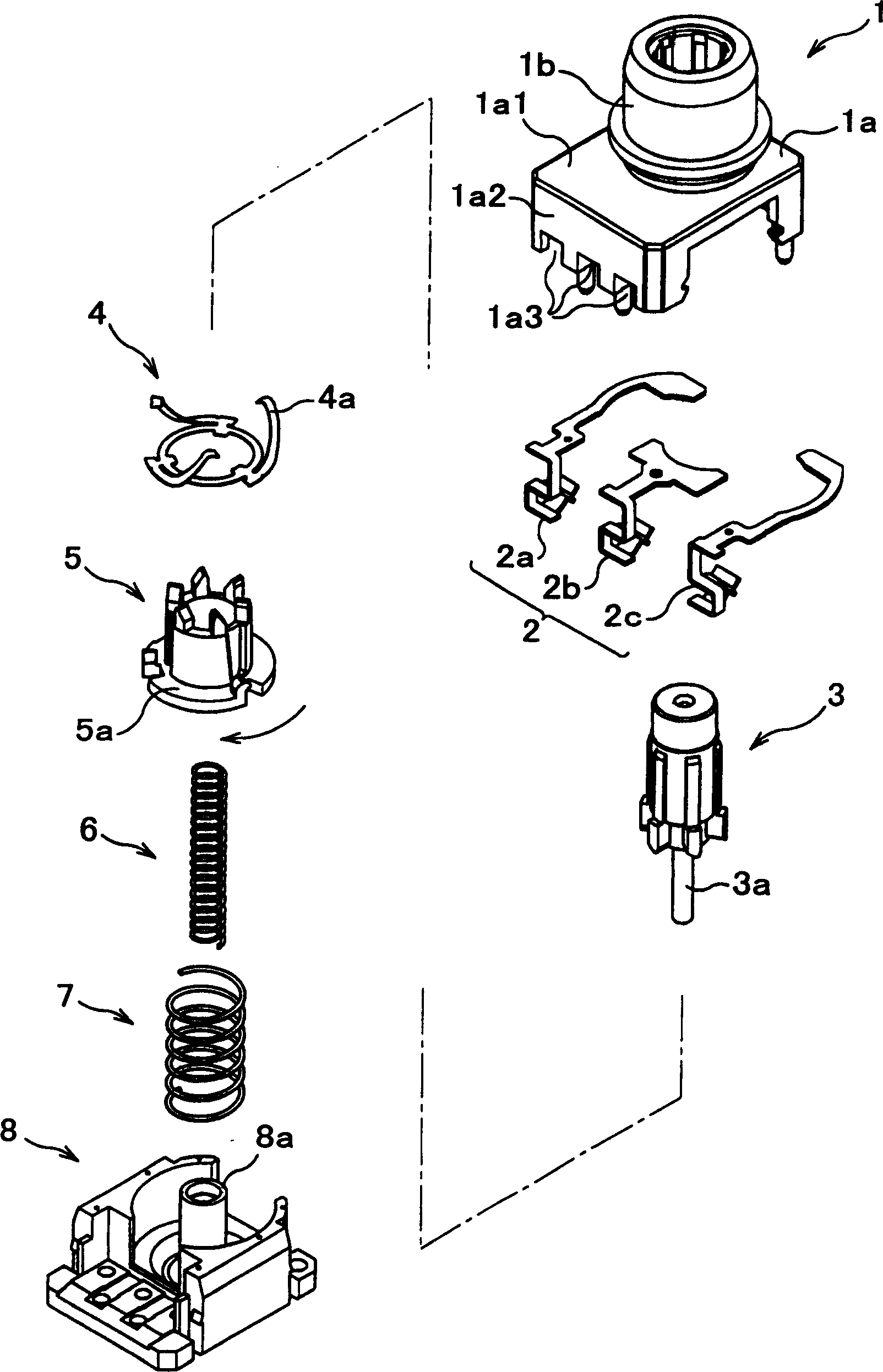
[0085] The following will refer to figure 1 The push button switch in the first embodiment of the present invention will be described. The push button switch according to this embodiment includes:

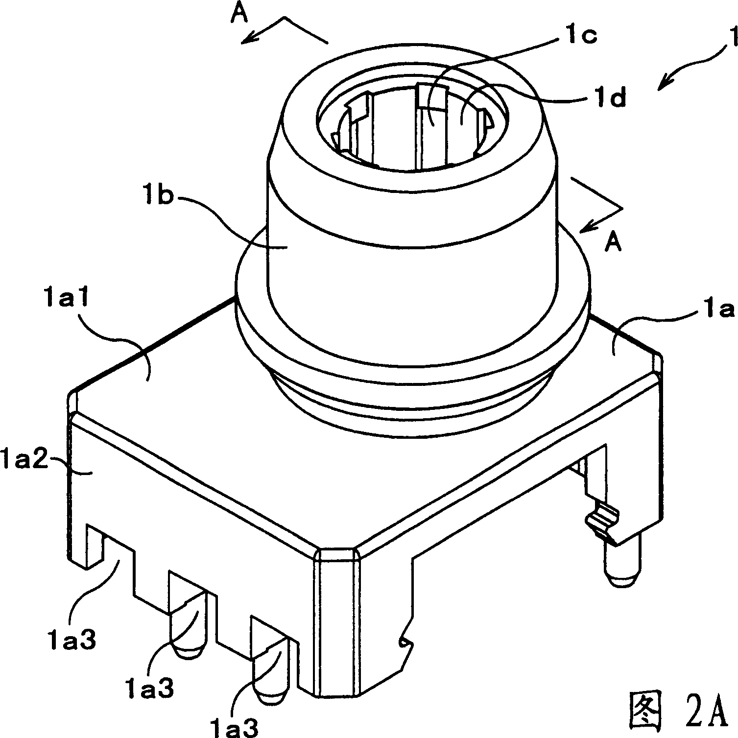
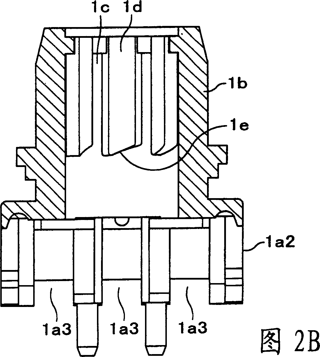
[0086] A substantially square housing 1a; an upper housing 1 having a substantially cylindrical cylindrical portion 1b disposed in said housing 1a; three stationary terminals 2a, 2b, 2c, which The stationary terminal is made of conductive material, and is in contact with a contact portion 4 to be mentioned below; a button 3, which is approximately cylindrical and is adapted to be installed in the cylindrical portion 1b so as to be able to move along the cylindrical portion 1b. The inner surface of 1b slides in the vertical direction, and a guide rod 3a extends from the bottom of the button; a contact part 4, which is made of conductive material and is generally flat ring-shaped, and the contact part 4 is made of The flange 5a of the rotor 5 to be mentioned below is locked, and t...

no. 2 example

[0142] The following will refer to Figure 13 to Figure 1 5 to describe the push button switch in the second embodiment of the present invention in detail. Such as Figure 13 As shown, the structure of the push button switch in this embodiment is similar to that of the first example, however, the difference lies in the stationary terminals 2a, 2b, 2c connected to the wires 9a, 9b, 9c. Such as Figure 14A As shown, the stationary terminals 2a, 2b, 2c include flat surface portions 2a1, 2b1, 2c1 similar to the first embodiment, and these stationary terminals are connected to the arms 4a ( Figure 5A , 5B, 5C) and the cable clamping mouth 2a2, 2b2, 2c2 are in contact, and the wires 9a, 9b, 9c are fixed to the said cable clamping mouth. As shown in Fig. 14B and Fig. 14C, the core wire 9a2, 9b2, 9c2 protruding from the end of the insulating shell 9a1, 9b1, 9c1 of the wire is compressed through the cable clamping port 2a2, 2b2, 2c2, and is connected with the cable The clamping op...


PUM


Abstract

A push-button switch includes: the upper tract, which has cylinder, push-button, which can slide along the cylinder, rotor, which has a flaunching at its bottom, slides to and fro with the removal of the push-button, sets the axis of rotation as the long axes of the cylinder and runs in preconcerted direction. The contacting part is inserted into the rotor and fixed by the flaunching. Multiple statistic terminals are facing with the abovementioned contacting part and have terminal part or cable clamping meatus. The lead is fixed on the cable clamping meatus. The rotor will run a certain angle with the to and fro motion of the push-button to realize the alternative switching of the 'on / off'. The arm of the contacting part bends over the statistic terminal. The abovementioned arms will happen the elastic bending with the change of distance between the statistic terminal and rotor to make the statistic terminal contact with the contacting part.

Description

technical field [0001] The present invention relates to a push button switch, and more particularly, to a push button switch whose contact points are actuated by axially disposed cams. Background technique [0002] Various forms of pushbutton switches have been proposed in the prior art in which the contact points are actuated by axially disposed cams. [0003] For example, in JP-A-2-72526, a method such as Figure 16 to Figure 22 pushbutton switch shown. [0004] Figure 16 Shows an exploded perspective view of the push button switch described in JP-A-2-72526, which includes: [0005] A driver housing 101, which has: a substantially cylindrical passage 101a in which a button 100 mentioned below or the like is installed; said button 100 has a cylindrical Cylindrical part 100a (see Figure 18B ), the cylindrical portion 100a is combined with said channel 101a; a driver cam follower 102 has a cylindrical square cavity portion 102a inside it, a rotating contact carrier 104 ...

Claims


Application Information

Patent Timeline
Patent Type & Authority Patents(China)
IPC IPC(8): H01H13/56H01H13/58H01H19/63
Inventor 三木亨
Owner MIYAMA ELECTRIC CO LTD
Learn More