
Method for preventing chip repetition deposition

A wafer reset technology, applied in instruments, electrical digital data processing, electrical components, etc., can solve problems such as wafer scrapping, repeated deposition, and poor contact of cassettes

Inactive Publication Date: 2007-04-25
MACRONIX INT CO LTD
View PDF3 Cites 0 Cited by
  • Summary
  • Abstract
  • Description
  • Claims
  • Application Information

AI Technical Summary

Problems solved by technology

However, some machines will send a status reset signal due to poor contact of the current micro switch of the cassette
At this time, the deposited wafers will be repeatedly deposited due to the status reset signal, which may even cause the wafers to be scrapped

Method used


Image

  • Method for preventing chip repetition deposition
  • Method for preventing chip repetition deposition

Examples


Embodiment Construction

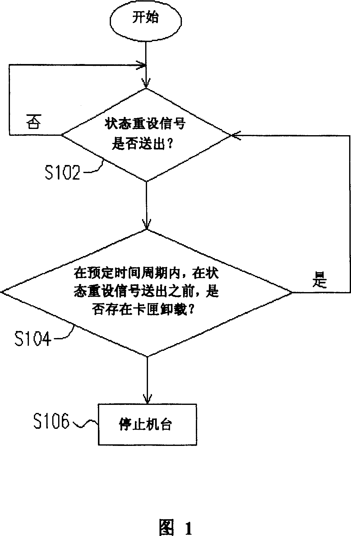
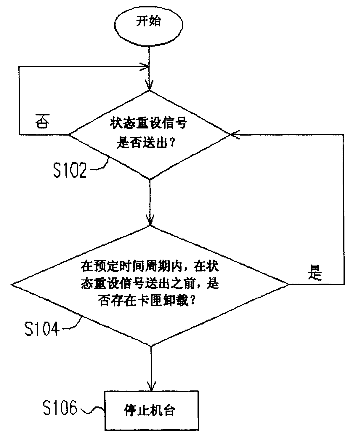
[0013] Currently, in a semiconductor factory, the transmission between semiconductor devices is based on the Semiconductor Equipment Communication Standard (SECS for short). The principle of the method for preventing repeated wafer deposition of the present invention is to use the state reset signal sent by the machine (for example: the event identification (event ID) 856 signal in SECS or the event identification 1856 signal in SECS) and the cassette unloading signal (eg: event recognition 51 signal in SECS). When the machine is in normal operation, it will not send the cassette unloading signal, only when picking up the goods, press unload (the cassette unloading signal will be sent), and the cassette in the machine will be taken out (the status reset signal will be sent ) will only appear. Therefore, the present invention utilizes the status reset signal and the cassette unloading signal to make a judgment. If only the status reset signal appears alone when the machine is ...


PUM


Abstract

A method for preventing chip reduplicated deposition wherein two kinds of signal are inspected, i.e. state reset signal and card box discharging signal. If the card box discharging signal does not exist within the predetermined time cycle before the state reset signal is sent out, the machine will be shut off to prevent chip reduplicated deposition. Otherwise, the machine will be reset for the execution of deposition operation.

Description

technical field [0001] The present invention relates to a method for preventing repeated deposition of wafers, and in particular relates to a method for preventing repeated deposition of wafers which stops operation of a machine when only a state reset signal appears. Background technique [0002] In the semiconductor manufacturing process, wafers are usually placed in cassettes, and then the cassettes are placed on various machines to perform a series of processes. As far as the current machine is concerned, when the machine sends a status reset signal, it will reset the machine. Generally speaking, when all the wafers in the cassettes of a certain machine have been deposited, the machine will send a status reset signal, at this time the cassette storing the wafers can be removed from the machine, and the machine will be reset . However, some machines will send a status reset signal due to poor contact of the current micro switch of the cassette. At this time, the deposi...

Claims


Application Information

Patent Timeline
Patent Type & Authority Patents(China)
IPC IPC(8): G06F11/00H01L21/00
Inventor 郑穆远
Owner MACRONIX INT CO LTD
Learn More