Internal battery holding structure in mobile equipment

A technology with built-in batteries and batteries, which is applied to the structure of telephones, small-sized batteries/battery packs, structural parts, etc., and can solve the problems of easily damaged battery covers and disconnected wires.

Inactive Publication Date: 2002-08-21
PANASONIC CORP
View PDF0 Cites 7 Cited by
  • Summary
  • Abstract
  • Description
  • Claims
  • Application Information

AI Technical Summary

Problems solved by technology

Alternatively, wire 46 may be cut or connector 53 may be disconnected
[0009] (3) Since the vibration of th

Method used


Image

  • Internal battery holding structure in mobile equipment
  • Internal battery holding structure in mobile equipment
  • Internal battery holding structure in mobile equipment

Examples


Embodiment Construction

[0022] Embodiments of the present invention will be specifically described below in conjunction with the accompanying drawings.

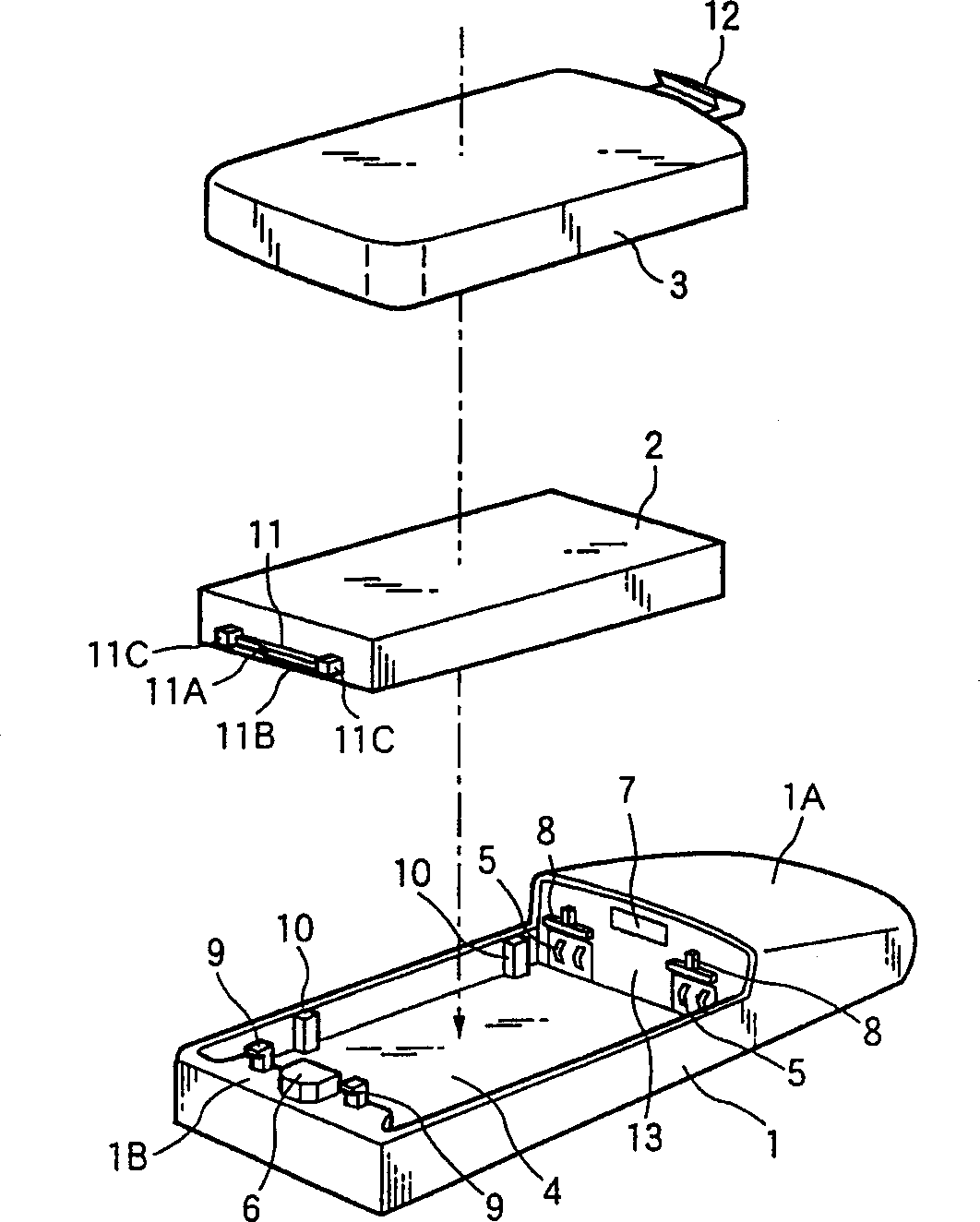
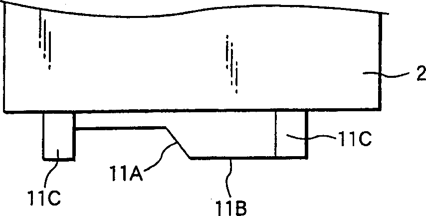
[0023] figure 1 is a perspective view schematically showing a built-in battery holding structure according to an embodiment of the present invention. Such as figure 1 As shown, the built-in battery 2 is placed in the recessed battery box portion 4 on the rear case 1 of the mobile phone, and then the battery cover 3 is mounted to the rear case 1 from above. Thus, the built-in battery 2 is incorporated into the mobile phone.

[0024] The battery case portion 4 is concave downward and is formed in a substantially rectangular parallelepiped shape on the surface of the rear case 1 . The inner wall surface on the front end is provided with a pair of connectors 5 , a rectangular fitting hole 7 , and a pair of first engaging protrusions 8 . A pair of connector terminals is exposed on the surface of the connector 5 . The first engaging protrusion 8 pr...


PUM


Abstract

An internal battery (2) has a battery terminal provided on a tip and has a third engagement projection (11) provided on the other end in a vertical direction. A battery housing portion (4) has a connector (5) provided on a tip and has, on a rear end, a battery hook (6) for pressing the third engagement projection (11) interlockingly with a sliding operation from a release position to a lock position. The battery hook (6) is slid from the release position to the lock position to press the third engagement projection (11). Consequently, the battery terminal is caused to abut on the connector (5) and the internal battery 2 is fixed into the battery housing portion (4). A battery (3) is fixed and attachment is thus completed.

Description

technical field [0001] The present invention relates to mobile devices such as mobile phones, and more particularly to a holding structure for a detachable built-in battery. Background technique [0002] Figure 8 A holding structure of a currently used removable built-in battery is shown. Such as Figure 8 As shown, the built-in battery 42 is placed in the recessed battery compartment portion 44 of the rear case 41 of the mobile phone, and then, the battery cover 43 is mounted to the rear case 41 from above. Thus, the built-in battery 42 is built into the mobile phone. Hereinafter, the longitudinal direction of the rear case 41 is referred to as the vertical direction, the direction perpendicular to the longitudinal direction of the rear case 41 along the bottom surface of the battery case portion 44 is referred to as the transverse direction, and the direction perpendicular to the bottom surface of the battery case portion 44 is called the heig...

Claims


Application Information

Patent Timeline
IPC IPC(8): H05K7/12H01M50/202H01M50/244H01M50/264H01M50/553H04M1/02H04W88/02
CPCH01M2/30H01M2/1066H04M1/0262H01M2/1022Y02E60/10H01M50/264H01M50/202H01M50/553H01M50/244
Inventor 海保贵志池田容伸十代干太佐藤建
Owner PANASONIC CORP
Why Eureka
Try Eureka