Intramedullary nail

An intramedullary nail and screw technology, applied in the field of intramedullary nails

Inactive Publication Date: 2002-11-06
SYNTHES GMBH
View PDF1 Cites 13 Cited by
  • Summary
  • Abstract
  • Description
  • Claims
  • Application Information

AI Technical Summary

Problems solved by technology

The disadvantage of this configuration is that the two hip screws (femoral head screw and hip pin) housed in the femoral head are inserted into the cylindrical hole of the intramedullary nail with stable angle

Method used


Image

  • Intramedullary nail
  • Intramedullary nail
  • Intramedullary nail

Examples


Embodiment Construction

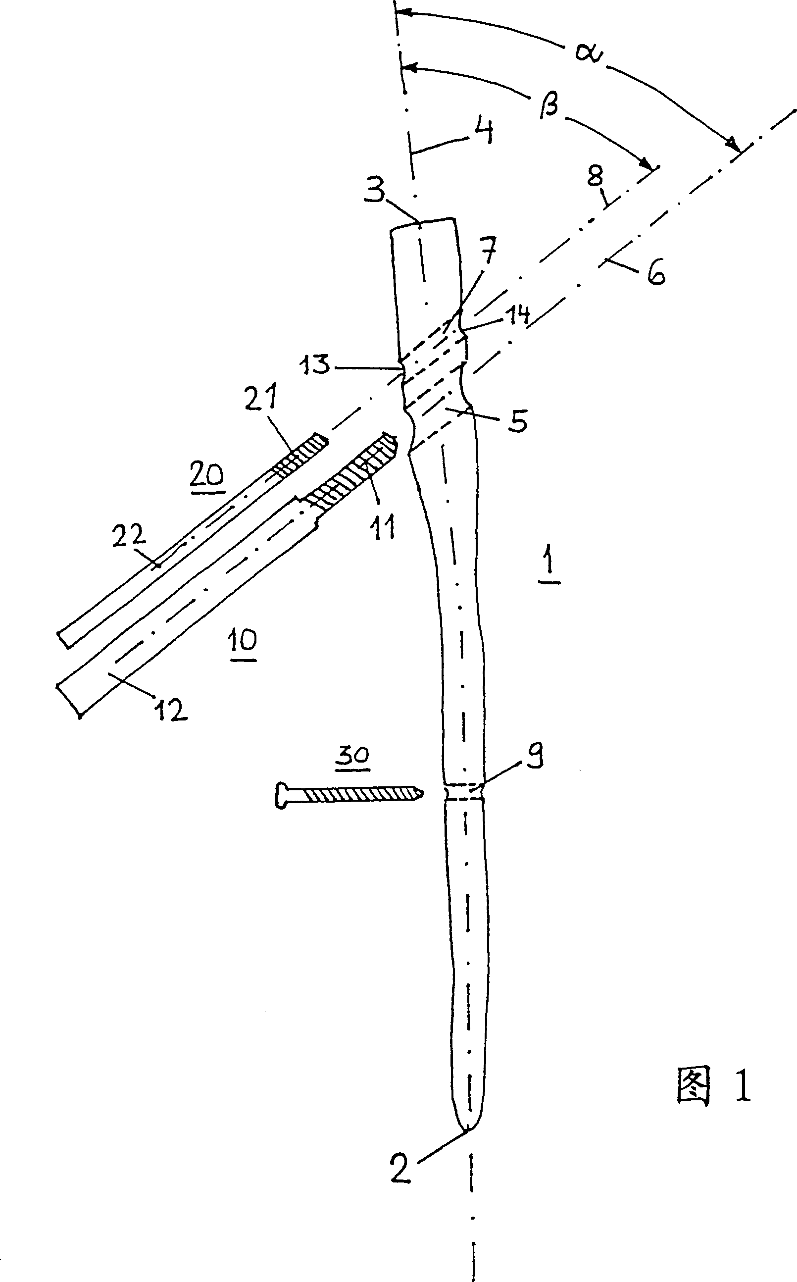
[0024] The intramedullary nail 1 shown in FIGS. 1 and 4 for treating femoral fractures has a distal end 2 , a proximal end 3 and a longitudinal axis 4 defined for insertion into the canal of the medullary canal. Furthermore, the intramedullary nail 1 has a first bore 5 with a longitudinal axis 6 , which intersects the longitudinal axis 4 , adjacent to the proximal end 3 , and which is intended to receive a femoral head screw 10 . The center line 6 of the first cylindrical hole 5 intersects the longitudinal axis 4 at an angle α of 30° to 70°, or at an angle 180°-α of 110° to 150°. Secondly, the intramedullary nail 1 is also provided with a second hole 7 with a longitudinal axis 8 transversely intersecting the longitudinal axis 4 between the first hole 5 and the proximal end 3 for accommodating a hip pin 20 . The center line of the second hole forms an angle β of 45° with the longitudinal axis.

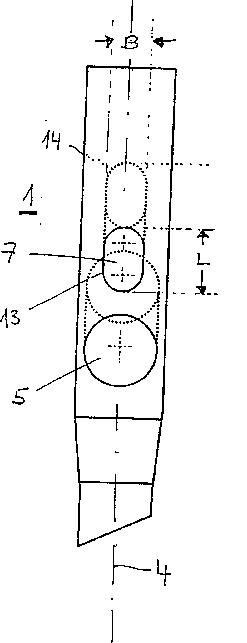
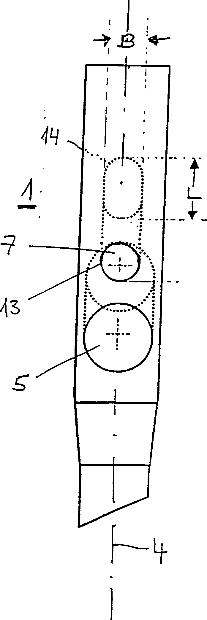
[0025] Such as figure 2 As shown, the side inlet 13 and the middle outlet 14 of t...


PUM


Abstract

The invention relates to an intramedullary nail used for treating fractures of the femur. It comprises a distal end, which is appointed for insertion into the marrow cavity channel, a proximal end, and a longitudinal axis. A first bore is located adjacent the proximal end and extends through the proximal end and transversely intersects the longitudinal axis, and serves to accommodate a femoral head screw. The center axis of the first bore forms an angle with the longitudinal axis that ranges from 110° to 150°. A second bore is located between the first bore and the proximal end and extends through the proximal end and transversely intersects the longitudinal axis, and serves to accommodate a hip pin. The second bore is at least partially shaped as an oblong hole or slot with a width B and a length L>B, and the length L of the oblong hole extends in the direction of the longitudinal axis.

Description

technical field [0001] The invention relates to an intramedullary nail according to the preamble of claim 1 . Background technique [0002] An intramedullary nail of this type is known from EP-A 0 551 588 . The disadvantage of this configuration is that the two hip screws (femoral head screw and hip pin) housed in the femoral head are inserted into the cylindrical hole of the intramedullary nail with stable angle. Due to the difference in their size-dependent flexural strength, it is clinically possible for the two screws to move relative to each other. Due to poor axial sliding or even seizure of the smaller hip pin, it may penetrate the hip joint. Contents of the invention [0003] The present invention proposes some improvements here. The object of the present invention is to create an intramedullary nail which does not have the above-mentioned disadvantages. [0004] The invention achieves the stated object with an intramedullary nail having the features of claim 1...

Claims


Application Information

Patent Timeline
Patent Type & Authority Applications(China)
IPC IPC(8): A61B17/58A61B17/74A61B17/78
CPCA61B17/744
Inventor 罗伯特·弗里格彼得·布伦纳
Owner SYNTHES GMBH
Why Eureka
Try Eureka