Locking mechainsm for jet injector

Inactive Publication Date: 2002-11-27
ANTARES PHARMA
View PDF7 Cites 3 Cited by
  • Summary
  • Abstract
  • Description
  • Claims
  • Application Information

AI Technical Summary

Problems solved by technology

A longer injection time can cause discomfort to the patient during the injection proces

Method used


Image

  • Locking mechainsm for jet injector
  • Locking mechainsm for jet injector
  • Locking mechainsm for jet injector

Examples


Embodiment Construction

[0056] For the convenience of description, in the drawings, the same or equivalent elements in the shown embodiments of the present invention use the same reference symbols. In addition, in the following description, any reference to orientation or direction is mainly for convenience of description rather than limiting the scope of the present invention thereto.

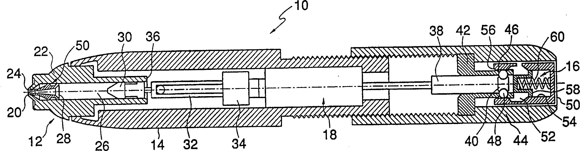
[0057] Such as figure 1 As shown, a jet injector 10 according to the present invention includes a nozzle assembly 12 mounted to a housing 14 . In this application, the term "distal" refers to the end or direction towards the front of the syringe 10 . The term "proximal" refers to the end or direction towards the rear of the syringe. The term "longitudinal" refers to an axis connecting nozzle assembly 12 and jet injector 10, and the term "transverse" refers to a direction substantially perpendicular to the longitudinal direction, including arcs along the surface of jet injector 10 or nozzle assembly 12.

[0058] Th...


PUM


Abstract

The present invention discloses a needle-assisted injector (10), which has a locking mechanism to reduce inadvertent contact with the needle (20) and prevent the needle from being reused intentionally. Upon activation of the power source, a portion of the needle extends through the nozzle assembly (12) and penetrates the outer layer of the skin to deliver the medicament to a deeper area by jet injection. After activation, the needle retracts into the nozzle assembly. The locking mechanism consists of a needle holder (260) and a locking ring (700), which cooperate to prevent re-injection when the syringe is activated.

Description

field of invention [0001] The present invention relates to a locking mechanism for a drug delivery device, and more particularly to a locking mechanism for a jet injector equipped with a shorter needle to reduce inadvertent needle contact and prevent deliberate needle reuse. Background of the invention [0002] A variety of needleless syringes are known in the art. Examples of such syringes include the types disclosed in US Patent Nos. 5,599,302 to Lilley et al., 5,062,830 to Dunlap, and 4,790,824 to Morrow et al. Typically, these and similar syringes are under sufficient pressure to process the medication as a fine, high-velocity jet through the skin. [0003] Since skin is a tissue made up of multiple layers, the syringe is applied to the outer surface of the outermost layer, and the advancing pressure must be high enough to penetrate all layers of the skin. The layers of the skin include: the epidermis, the outermost layer of the skin, the dermis, and the subcutaneous r...

Claims


Application Information

Patent Timeline
IPC IPC(8): A61M5/20A61M5/24A61M5/30A61M5/32A61M5/50
CPCA61M5/24A61M5/30A61M5/3232A61M5/326A61M5/3286A61M5/50A61M2005/3247
Inventor 小保罗·R·莱施
Owner ANTARES PHARMA
Why Eureka
Try Eureka