
Method and device for reproducing data recorded on optical disk

A technology for reproducing optical discs and optical discs, applied in optical recording/reproducing/erasing methods, reproducing non-user data, data recording, etc., capable of solving problems such as track width variation and deterioration

Inactive Publication Date: 2002-12-25
SAMSUNG ELECTRONICS CO LTD
View PDF1 Cites 0 Cited by
  • Summary
  • Abstract
  • Description
  • Claims
  • Application Information

AI Technical Summary

Problems solved by technology

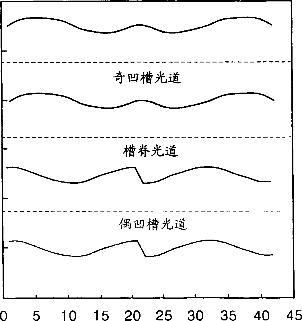
Therefore, during reproduction from the land track of the land / groove recordable optical disc proposed by the present applicant and as described above, the radio frequency (RF) reproduced by the conventional reproduction signal detection method ) signal deteriorates due to track width variation

Method used


Image

  • Method and device for reproducing data recorded on optical disk
  • Method and device for reproducing data recorded on optical disk
  • Method and device for reproducing data recorded on optical disk

Examples


Embodiment Construction

[0049] Referring to FIG. 6, FIG. 6 is a block diagram of a preferred embodiment of an optical disc reproducing apparatus according to the present invention, which includes a beam splitting and detecting unit 10 and a signal processor 20 so as to correct the degradation caused by the variation of the track width. A component of a high-quality reproduction signal is detected in reproduction from an optical disc having a varying track width. The basic structure of an optical pickup is known to those skilled in the art, in which a light beam is emitted onto a recording surface of an optical disc, and a light beam reflected from the recording surface of the optical disc is detected by a beam splitting and detecting unit 10 . Therefore, a detailed description and illustration of the basic structure of the optical pickup is not provided here.

[0050] The beam splitting and detecting unit 10 detects the beam reflected from the recording surface of the optical disc as a central beam p...


PUM


Abstract

A method and device for reproducing an optical disc are provided. In the optical disc reproducing method, a light beam reflected from a recording surface of an optical disc is split into a central beam portion and an outer beam portion in a direction corresponding to a radial direction of the optical disc, and the separated central beam and outer beam portions are detected, from A first detection signal of the central beam portion and a second detection signal from at least one of the outer beam portions are output. The amplitudes of the first detection signal and / or the second detection signal are adjusted, and the reproduction signal is detected by subtracting the first detection signal and the second detection signal, wherein at least the first detection signal and the second detection signal The amplitude of one of the two detection signals is adjusted. Therefore, when reproducing an optical disc having a varying track width, a reproduced signal with excellent performance can be detected from the optical disc.

Description

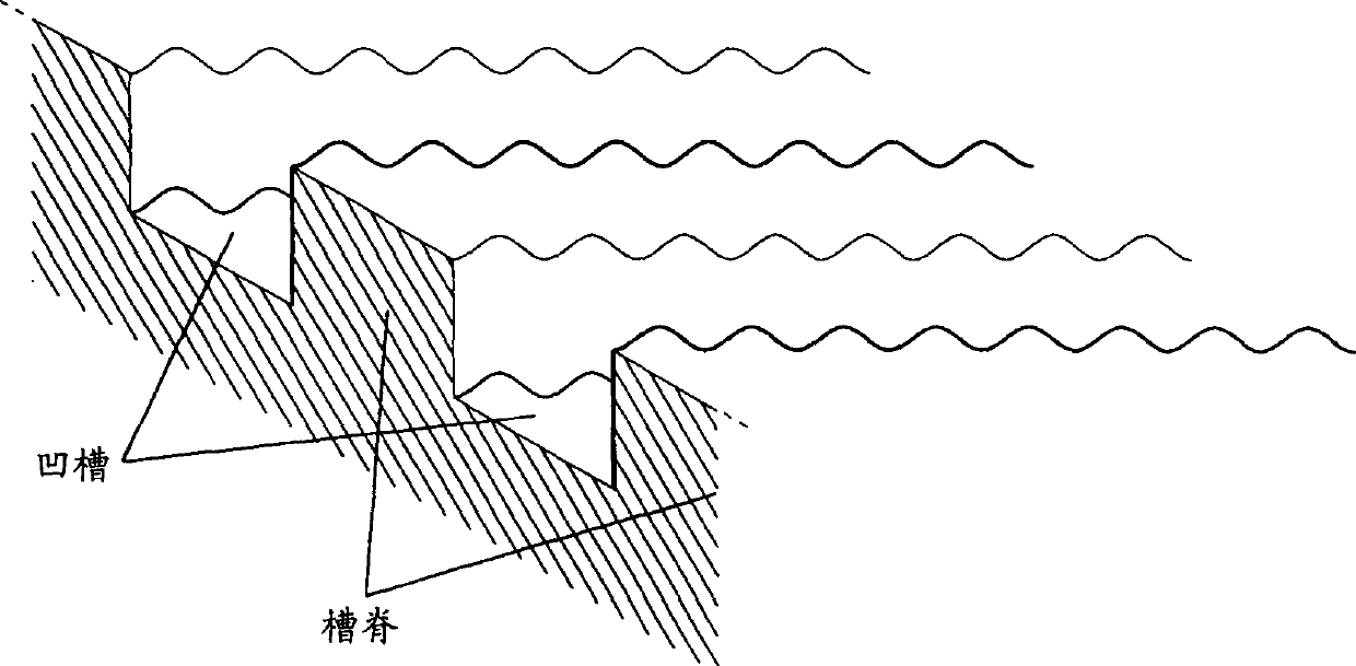
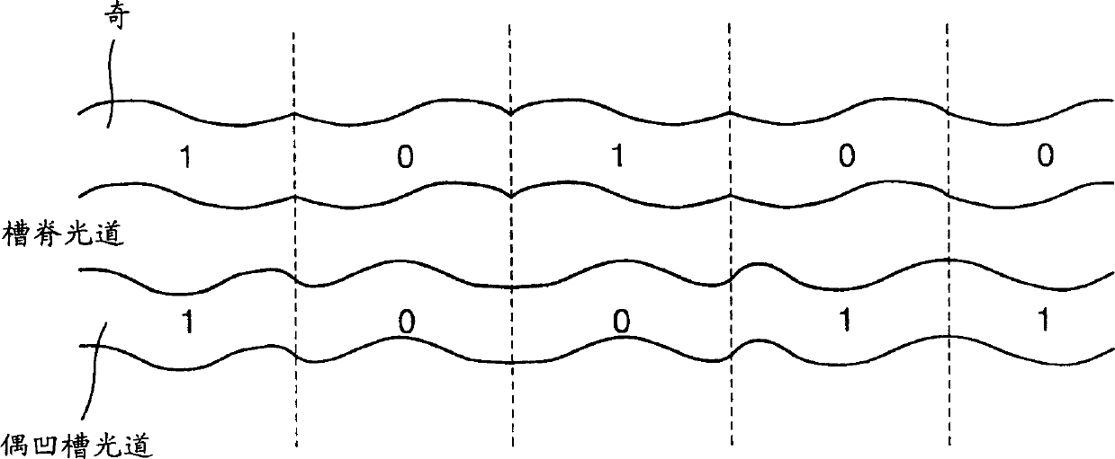
technical field [0001] The present invention relates to a method and a device for detecting a reproduced signal with high quality performance from an optical disc having varying track widths. Background technique [0002] A recordable optical disc, such as a CD-R, CD-RW, DVD-RAM, DVD-R, DVD-RW or DVD+RW, has guide grooves along its track to enable an optical pickup to precisely Track the desired track. The area of ​​the disc with the guide groove is called the "groove" and the remaining area is called the "land". The recording method of such an optical disc is classified into a method of recording user data on the land or groove of the optical disc, as is the case in CD-R / RW, DVD-R / RW, and DVD+RW, and in the groove of the optical disc. A method of recording user data on both lands and grooves, as is the case in DVD-RAM. [0003] In the manufacture of groove tracks and / or land tracks of recordable optical discs, by using changes in the amplitude di...

Claims


Application Information

Patent Timeline
IPC IPC(8): G11B7/24G11B7/005G11B7/007G11B7/13G11B7/131
CPCG11B7/0053G11B7/00718G11B7/00745G11B7/131G11B7/007
Inventor 金泰敬安荣万金钟培郑钟三
Owner SAMSUNG ELECTRONICS CO LTD
Learn More