Representation and diawing method of three-D target and method for imaging movable three-D target

A technology for 3D objects and images, applied in 3D image processing, image data processing, instruments, etc., can solve problems such as complex data structure, difficult construction, and complicated use

Inactive Publication Date: 2003-02-05
SAMSUNG ELECTRONICS CO LTD
View PDF0 Cites 31 Cited by
  • Summary
  • Abstract
  • Description
  • Claims
  • Application Information

AI Technical Summary

Problems solved by technology

Polygonal models have two major disadvantages: large capacity (eg, tens of millions of triangles for an ideal model) and difficulty in constructing
However, in [4] a somewhat complex and time-consuming truncated culling process is used
The data structure is also complex and takes more time to process

Method used


Image

  • Representation and diawing method of three-D target and method for imaging movable three-D target
  • Representation and diawing method of three-D target and method for imaging movable three-D target
  • Representation and diawing method of three-D target and method for imaging movable three-D target

Examples


Embodiment Construction

[0048] In all the figures illustrating the invention, the same elements are identified by the same reference numerals.

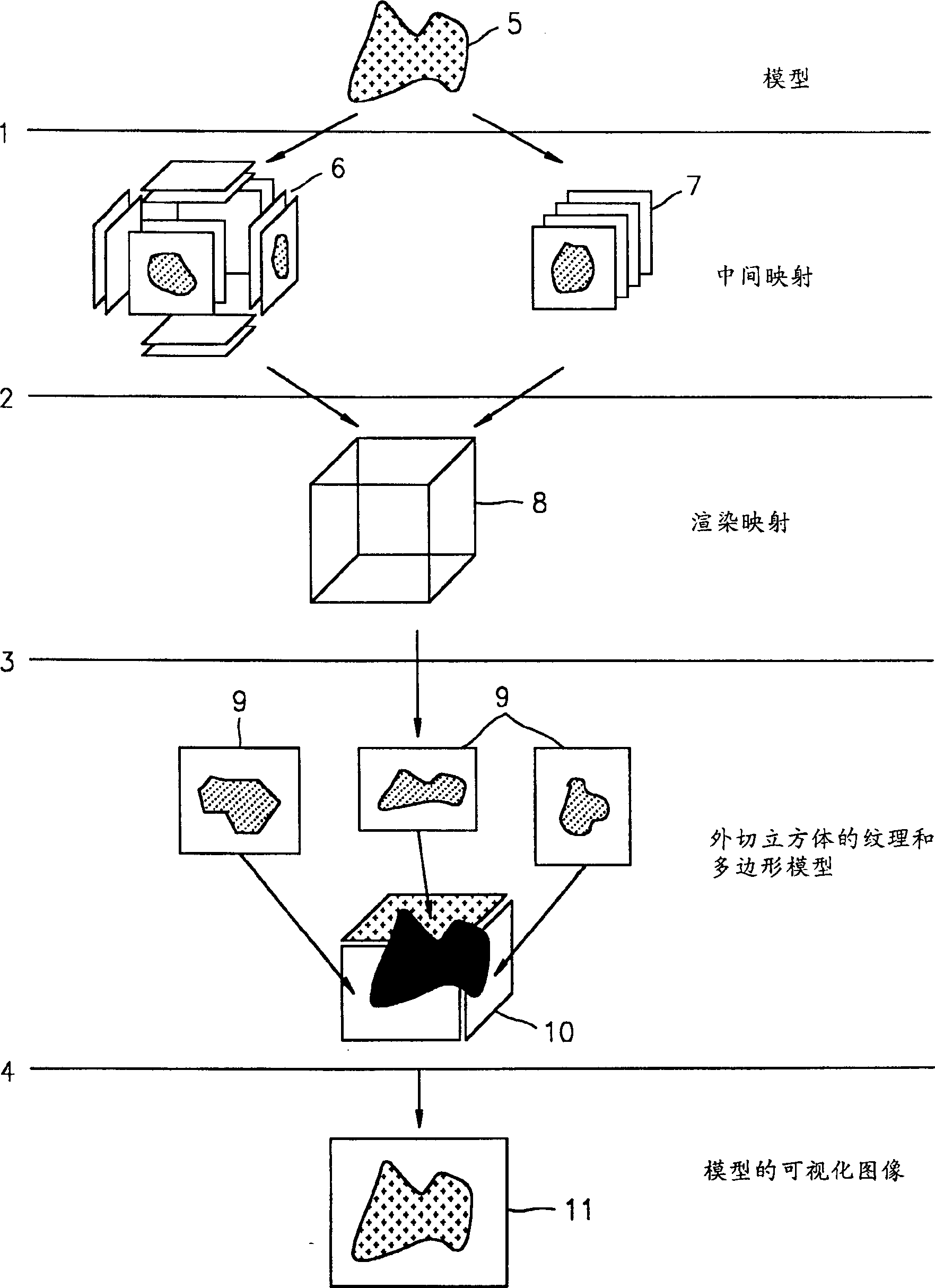
[0049] figure 1 Shown are: steps 1 to 4 of the method of mapping and rendering a three-dimensional object; a three-dimensional object model 5; intermediate maps 6, 7; render maps 8; textures 9; polygonal models 10 of circumscribed cubes;

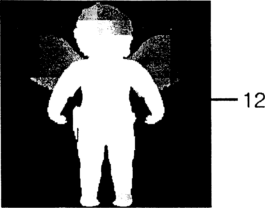
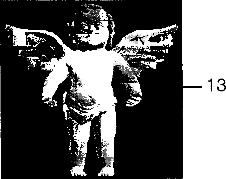
[0050] Figures 2a, 2b show a grayscale image 12 and a color image 13.

[0051] Figures 3a, 3b show the model 14, the base plate 15, the set of points 16 for each pixel of the layered depth image.

[0052] Figure 4 Shown are: cube surface 17 , point 18 of the render map, normal 19 at point 18 , visibility cone 20 .

[0053] Figure 5 Shown are: the position of the observer 21 , the orthogonal projection 22 of the point at the position of the observer onto the surface 17 , the quadrants 23 to 26 of the surface 17 , the directions of traversal 27 to 30 in each surface quadrant.

[0054] Figures 6a, 6b show: the angle 31...


PUM


Abstract

Provided are three-dimensional still and animated object representations obtained from photos of real-life objects and their geometrical representations, allowing compact storage, fast rendering with high output image quality, suitable for animation purposes. The method includes transforming original data of a three-dimensional object into an intermediate representation; transforming data of the intermediate representation into a rendering representation in the form of a circumscribing cube, where a layered depth image is attributed to each face of the circumscribing cube, and rendering the obtained representation by determining visible faces of the circumscribing cube with account of the viewer's position, transforming the layered depth image for each of the visible faces into a texture, and visualizing the visible faces with texture.

Description

technical field [0001] The present invention relates to computer graphics, and more particularly to three-dimensional (3D) mapping of stationary and moving objects obtained from photographs of real objects and their geometric mapping, and to methods of mapping and rendering using simplified geometric models of objects. Background technique [0002] In the near future, high-quality rendering of 3D objects at interactive speeds will dominate modern graphics display systems. The requirement for high-quality rendering of 3D objects necessitates devising efficient algorithms for compressing objects and transmitting them over communication networks in fields such as e-commerce, computer games, science, engineering, medicine, etc. In the past few decades, it has been difficult to give ideal results by using traditional 3D object polygonal models to meet these requirements at the same time. Polygonal models have two major disadvantages: they are large in ...

Claims


Application Information

Patent Timeline
Patent Type & Authority Applications(China)
IPC IPC(8): G06T15/04G06T15/20G06T17/00G06T17/10
CPCG06T15/205G06T15/04G06T17/10
Inventor 韩万阵亚历克西·伊格纳坦科
Owner SAMSUNG ELECTRONICS CO LTD
Why Eureka
Try Eureka