Ice machine
An ice making machine and ice making water technology, applied in the directions of ice making, refrigerator, ice making, etc., can solve the problems of difficulty in identification, shortened service life of screw-type ice machine, increased consumption of electricity and water, etc.
- Summary
- Abstract
- Description
- Claims
- Application Information
AI Technical Summary
Problems solved by technology
Method used
Image
Examples
Embodiment 1
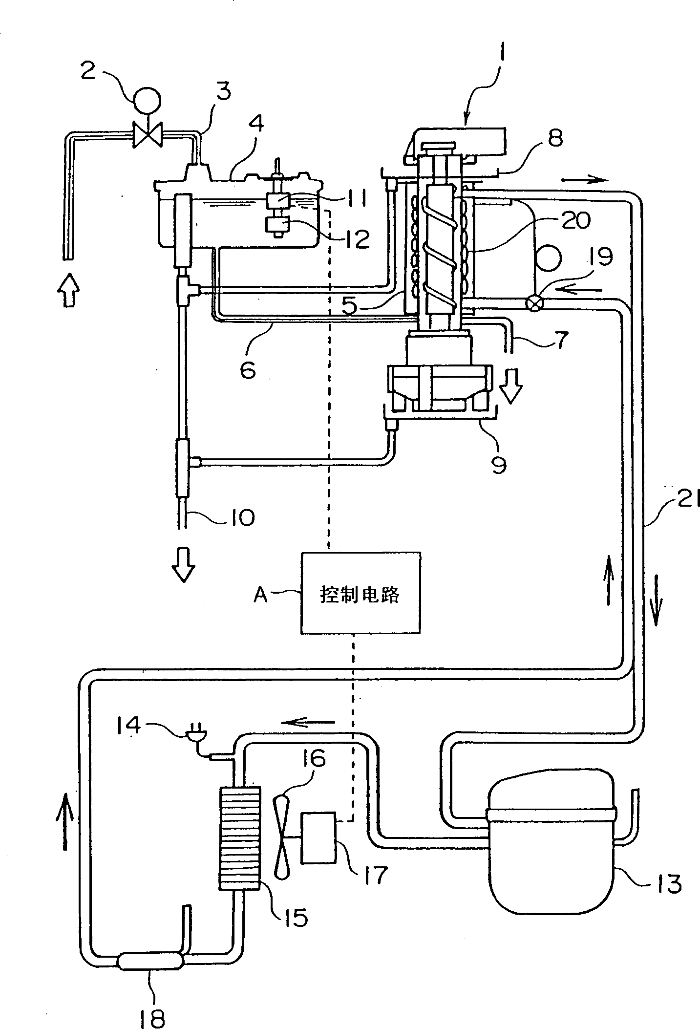
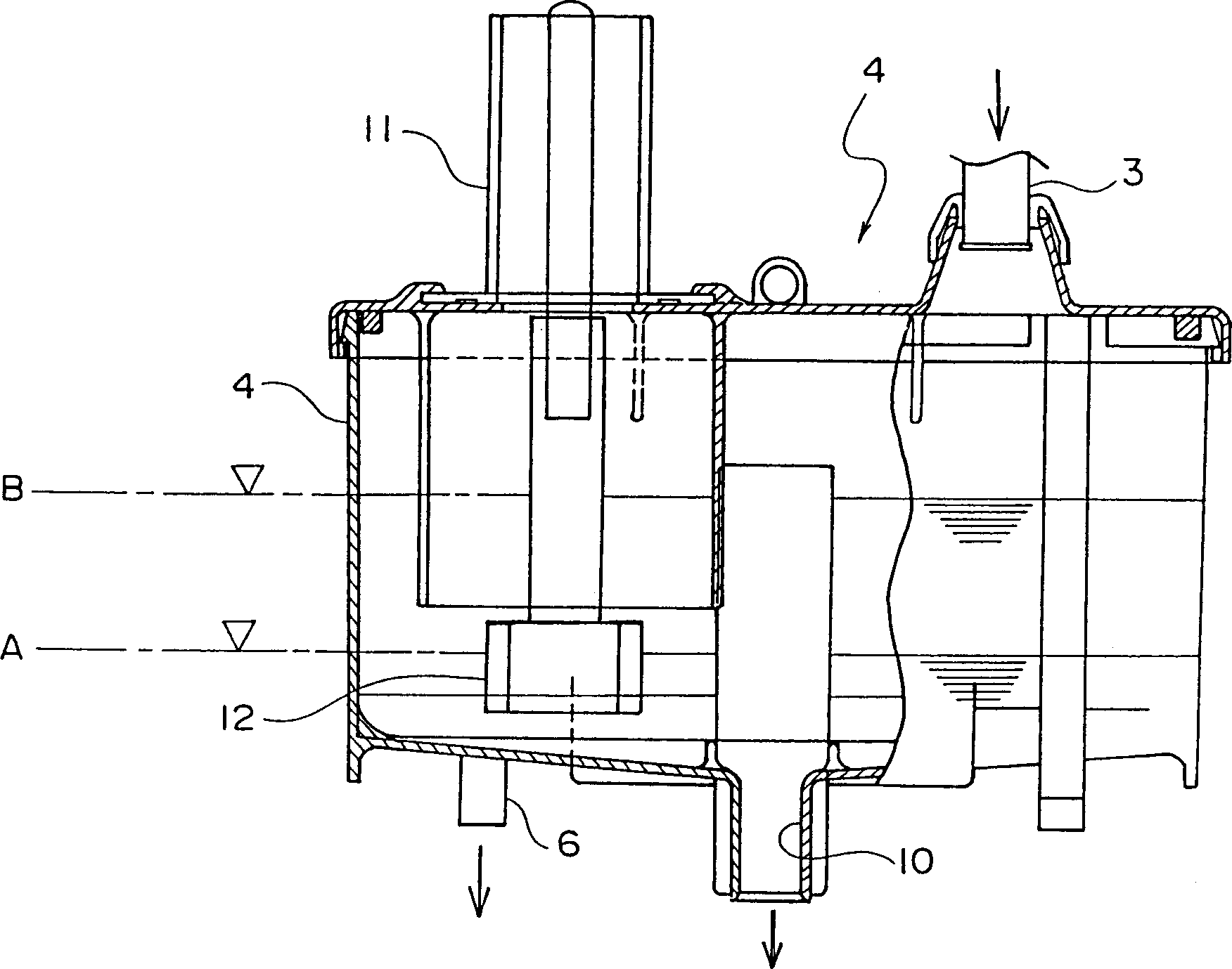
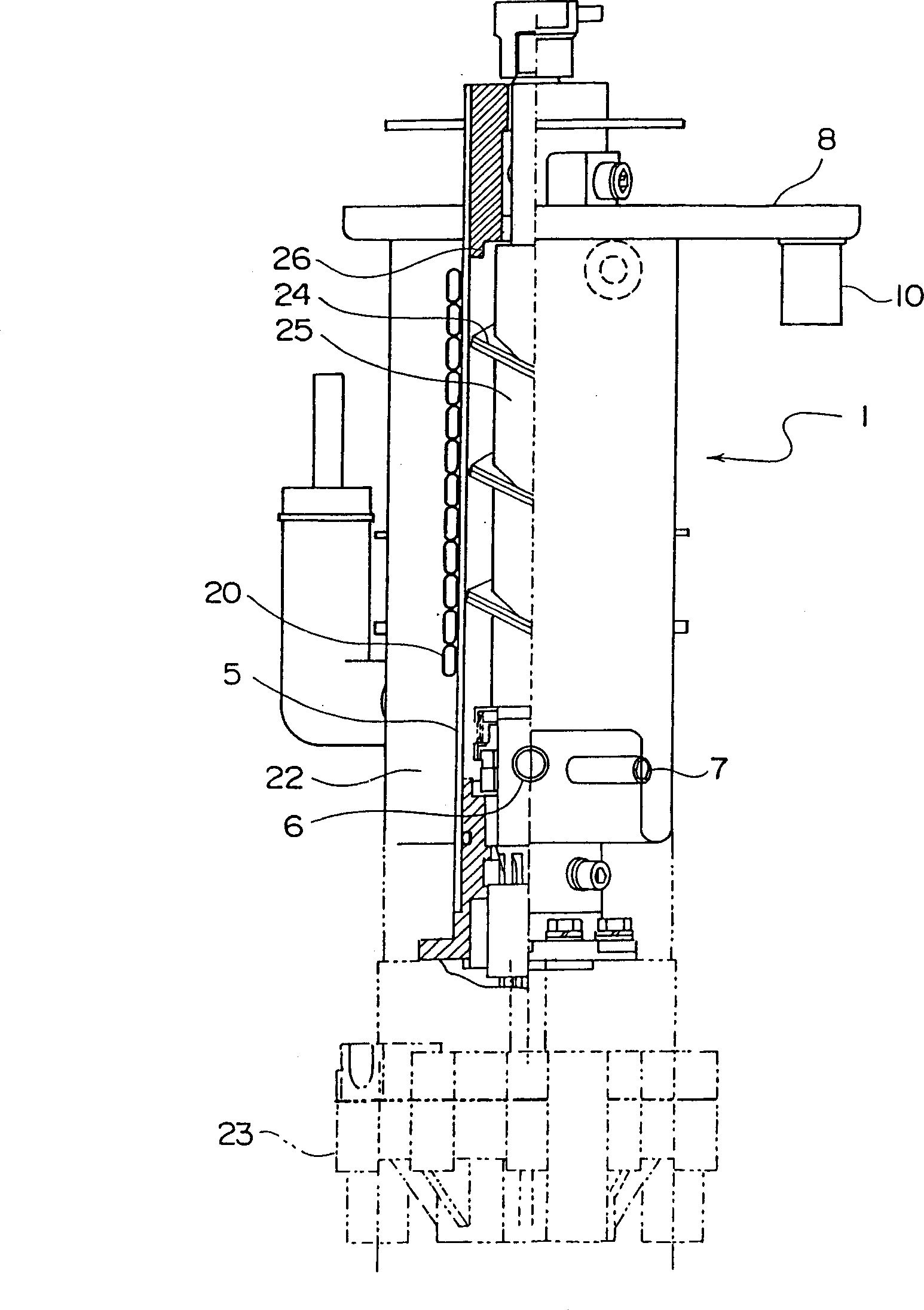
[0055] Below, according to Figure 1 to Figure 5 The illustrated Example 1 illustrates the invention in detail. figure 1 It is a diagram showing the water path and refrigeration circuit diagram of the screw ice maker used in this embodiment, figure 2 is a longitudinal section view of the water supply tank, image 3 It is a side view showing the ice making mechanism part of the spiral ice maker in partial longitudinal section. Figure 4 It is a flow chart showing the operation of the first embodiment. Figure 5 It is a time chart for explaining the water supply stop time of the water supply solenoid valve.
[0056] exist figure 1 and figure 2 In the following, the water path and refrigeration circuit diagram of the spiral ice maker used in Example 1 will be described. The water path of the spiral ice machine consists of a water supply solenoid valve 2, a water supply pipe 3, a water supply tank 4, a supply pipe 6 for supplying ice-making water to the cylinder 5, a dra...
Embodiment 2
[0066] Such as Figure 6 As shown, in Embodiment 2, a temperature sensor 27 for detecting the temperature of the condenser 15 is provided in the ice maker of Embodiment 1, and the temperature sensor 27 constitutes the ice-making capacity detection device of the present invention. Since the other configurations are the same as those of the first embodiment, only the different configurations will be described. The magnitudes of the measured temperature CT1 of the condenser 15 measured by the temperature sensor 27 and a certain arbitrary reference temperature CT2 are compared. When the measured temperature CT1 measured by the temperature sensor 27 is lower than the reference temperature CT2 , the control circuit A controls the rotation speed of the fan motor 17 to be low. As a result, the condensing capacity is intentionally lowered, and excess ice production is restricted.
[0067] Therefore, according to Example 2, as Figure 7 As shown in the flow chart of (the same steps a...
Embodiment 3
[0070] Such as Figure 8 As shown, embodiment 3 is that in the ice maker of embodiment 1, pressure sensors 28 and 29 for detecting the high-pressure side pressure and low-pressure side pressure of the compressor 13 are provided, and these pressure sensors 28 and 29 constitute the ice maker of the invention. Ice capacity detection device. Since the other configurations are the same as those of the first embodiment, only the different configurations will be described. The compression ratio A1 is calculated from the high-side pressure and the low-side pressure measured by the pressure sensors 28 and 29 , and the magnitude of the compression ratio A1 is compared with an arbitrary reference value A2 . When the compression ratio A1 is smaller than the reference value A2, the control circuit A controls the rotation speed of the fan motor 17 to decrease. As a result, the condensing ability is intentionally lowered, and excessive ice production is suppressed.
[0071] That is, if ...
PUM
 Abstract
Description
Claims
Application Information
 - R&D
- Intellectual Property
- Life Sciences
- Materials
- Tech Scout
- Unparalleled Data Quality
- Higher Quality Content
- 60% Fewer Hallucinations
Browse by: Latest US Patents, China's latest patents, Technical Efficacy Thesaurus, Application Domain, Technology Topic, Popular Technical Reports.
© 2025 PatSnap. All rights reserved.Legal|Privacy policy|Modern Slavery Act Transparency Statement|Sitemap|About US| Contact US: help@patsnap.com


