Butterfly brake of bicycle

A bicycle and butterfly brake technology, applied in bicycle accessories, bicycle brakes, etc., can solve problems such as drag torque, and achieve the effect of increasing the braking force

Inactive Publication Date: 2003-04-16
许艳
View PDF0 Cites 4 Cited by
  • Summary
  • Abstract
  • Description
  • Claims
  • Application Information

AI Technical Summary

Problems solved by technology

It completely solves the phenomenon that the brake disc is easy to contact with the friction plate to generate drag torque

Method used


Image

  • Butterfly brake of bicycle
  • Butterfly brake of bicycle
  • Butterfly brake of bicycle

Examples


Embodiment Construction

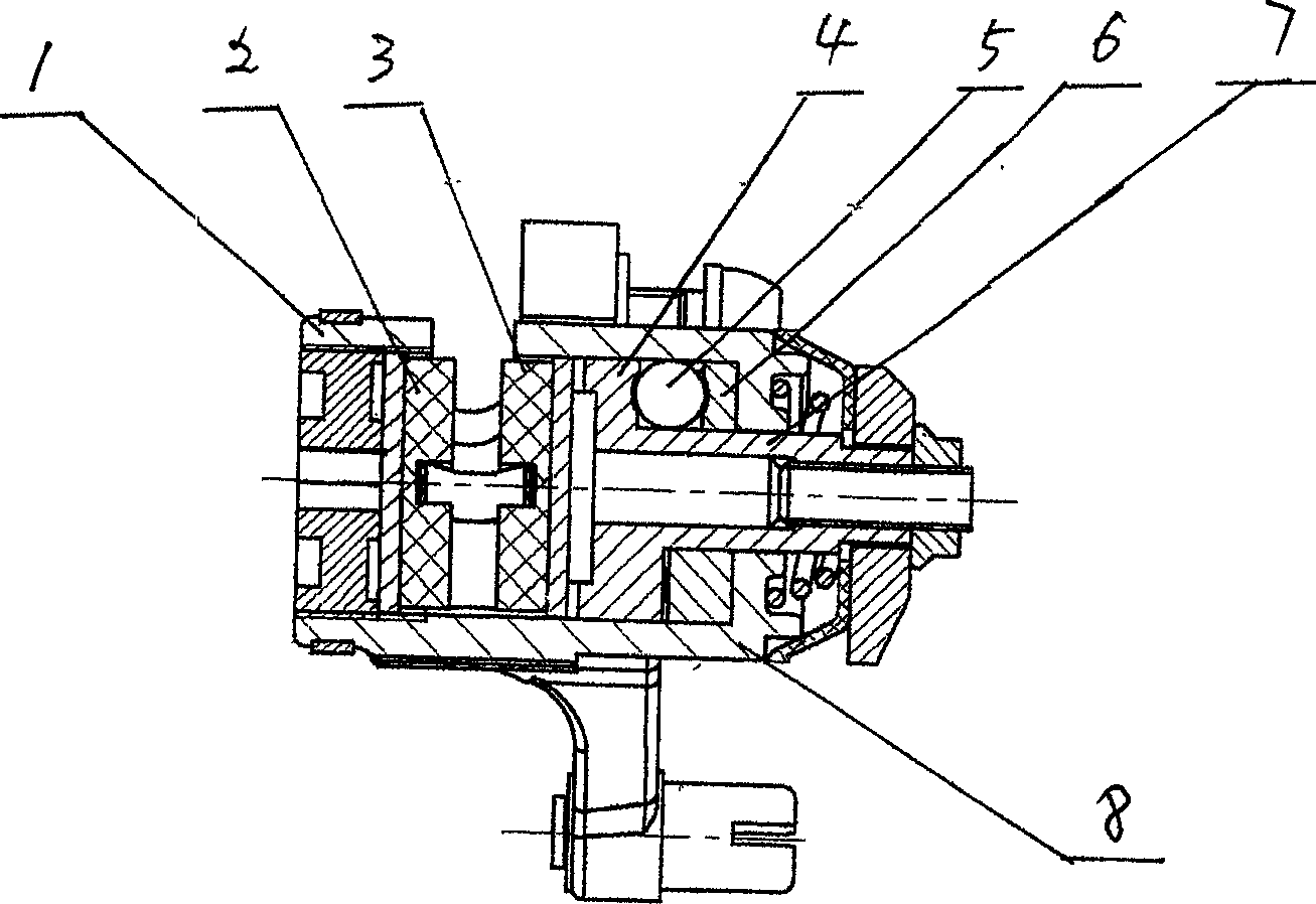
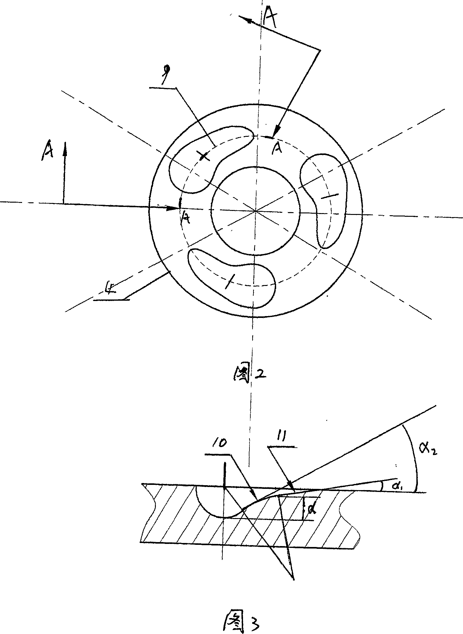
[0022] A bicycle butterfly brake, which includes a brake drive device 8 and a brake caliper body 1 fixedly connected with the brake drive device housing, in which the brake caliper body 1 is installed with left and right friction plate assemblies 2, 3, two friction plates Brake discs are installed between the components, and the brake discs and the wheel hub of the bicycle are fixedly installed. The brake stop drive device 8 includes a drive shaft 7 arranged in its housing and perpendicular to the friction plate, and a drive disc fixedly installed on the drive shaft 7. 4. As well as the fixed disk 6 that cooperates with the driving disk 4 through the rolling member 5, at least one of the disk surfaces of the driving disk 4 and the fixed disk 6 is axisymmetrically provided with three to four spiral slideways 9, the said The spiral slide 9 is composed of at least two spiral slides with different helix angles connected smoothly.

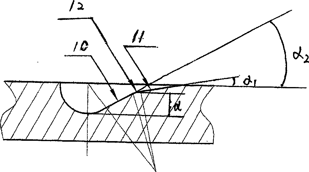
[0023] As shown in Figure 3, the spiral slideway ...


PUM


Abstract

A butterfly brake for bicycle is composed of brake driver and jaw body. The jaw body has left and right friction plates. The said brake driver consists of the drive axle perpendicular to the said friction plates and the driven disk matched with roll member to drive the drive axle. The drive disk has two different spiral slide ways for allowing the said roll member to move in them. Its advantages are big distance between two brake plates and high braking force.

Description

technical field [0001] The invention relates to a bicycle braking device, in particular to a bicycle butterfly brake. Background technique [0002] Bicycle butterfly brake, which includes a brake drive device and a brake caliper body fixedly connected with the brake drive device, left and right friction plate assemblies are installed in the brake caliper body, and a brake disc is installed between the two friction plate assemblies. It is fixedly installed with the wheel hub of the bicycle. Among the various butterfly brake products at home and abroad, most of the brake drive devices use rolling members to roll in the spiral slideway, and the driving force is generated through the helix angle of the spiral slideway to drive the friction plate. Hold tightly to the brake disc to achieve braking. At present, the most prominent problem is that during the running of the bicycle, the disc of the brake disc shakes a lot. In the non-braking state, the disc is...

Claims


Application Information

Patent Timeline
Patent Type & Authority Applications(China)
IPC IPC(8): B62L1/02
Inventor 许艳
Owner 许艳
Why Eureka
Try Eureka