

Antenna for contact-free transmission/reception reading system
Patent Information
- Authority / Receiving Office
- CN · China
- Current Assignee / Owner
- ASK CORP
- Publication Date
- 2003-06-18
- Estimated Expiration
- Not applicable · inactive patent
Smart Images
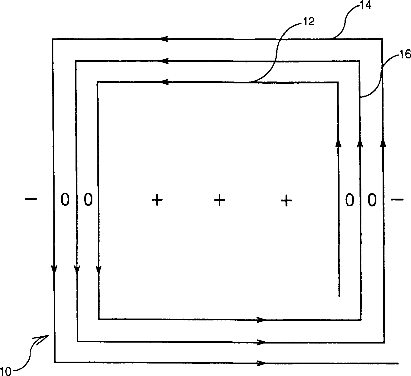
Figure 1 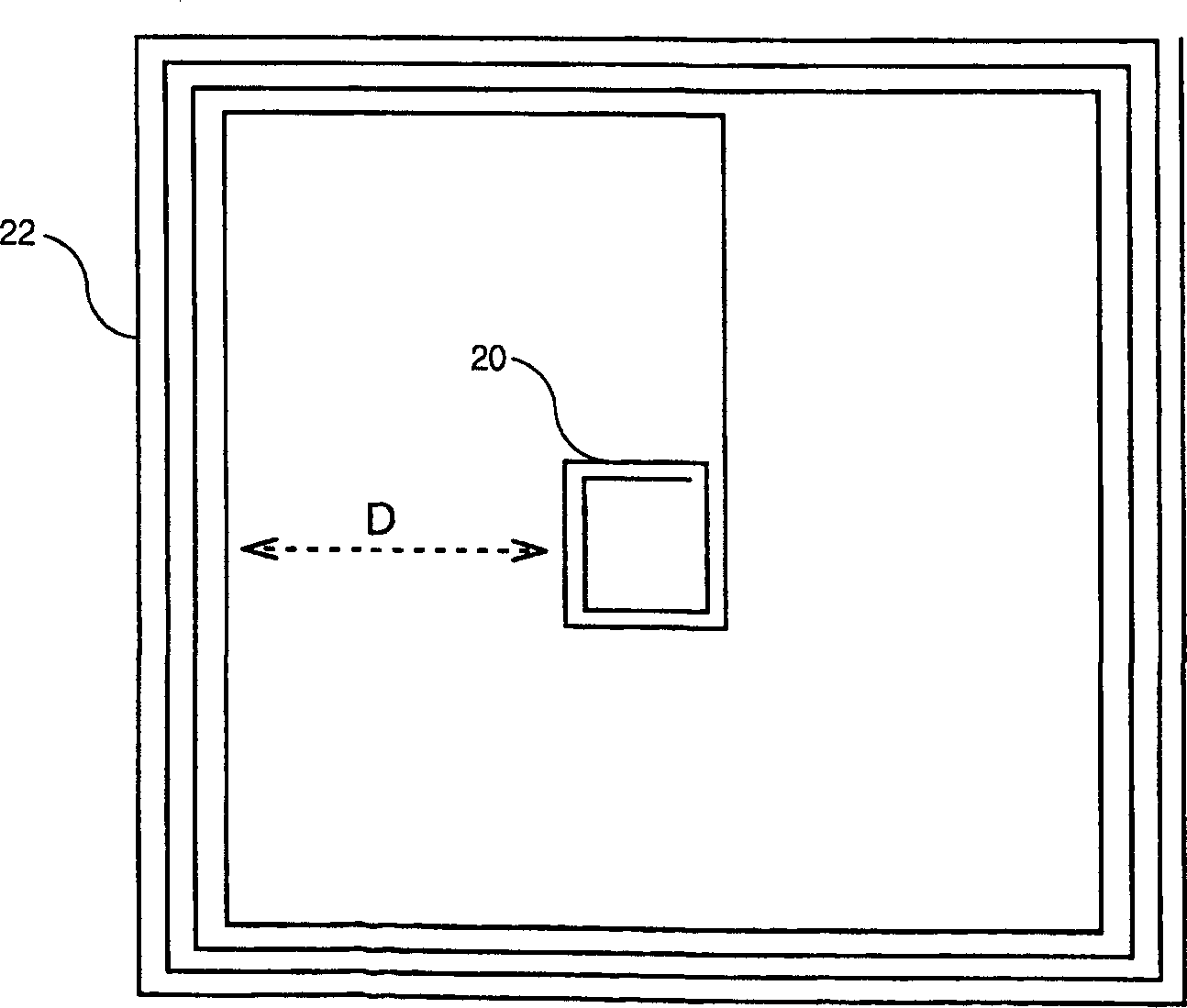
Figure 2 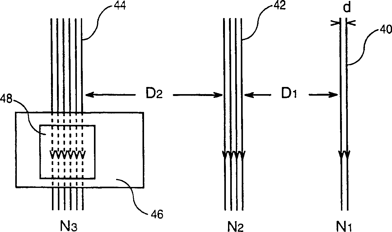
Figure 3
Abstract
Description
technical field
[0001] The present invention relates to transceiver systems using a reader designed to detect, in response to an electromagnetic signal emitted by an antenna located within the reader, a signal presented by its holder in front of the reader. Electromagnetic signals emitted by portable non-contact objects, and in particular the invention relates to a reader antenna for a non-contact transceiver system. Background technique
[0002] Carriers used to identify their holder or to enter controlled access areas, such as public transport networks (such as the RATP metro network or the SNCF metro network in France), are increasingly associated with standard contact bodies (cards or tickets) A different so-called "touchless" technology is featured.
[0003] The exchange of information between the non-contact body and the reader is usually achieved by remote electromagnetic coupling between a first antenna housed in the non-contact body and a second antenna located in ...