LED display panel

A technology of LED display panel and display panel, applied in optical components, optics, instruments, etc., can solve the problem of no visual change effect and so on

Inactive Publication Date: 2003-08-27
汪秉龙
View PDF0 Cites 6 Cited by
  • Summary
  • Abstract
  • Description
  • Claims
  • Application Information

AI Technical Summary

Problems solved by technology

[0006] The defective of above-mentioned LED display panel is: its diffusion image only has such as figure 2 one shown, and no other visual shifting effects

Method used


Image

  • LED display panel
  • LED display panel
  • LED display panel

Examples


Embodiment Construction

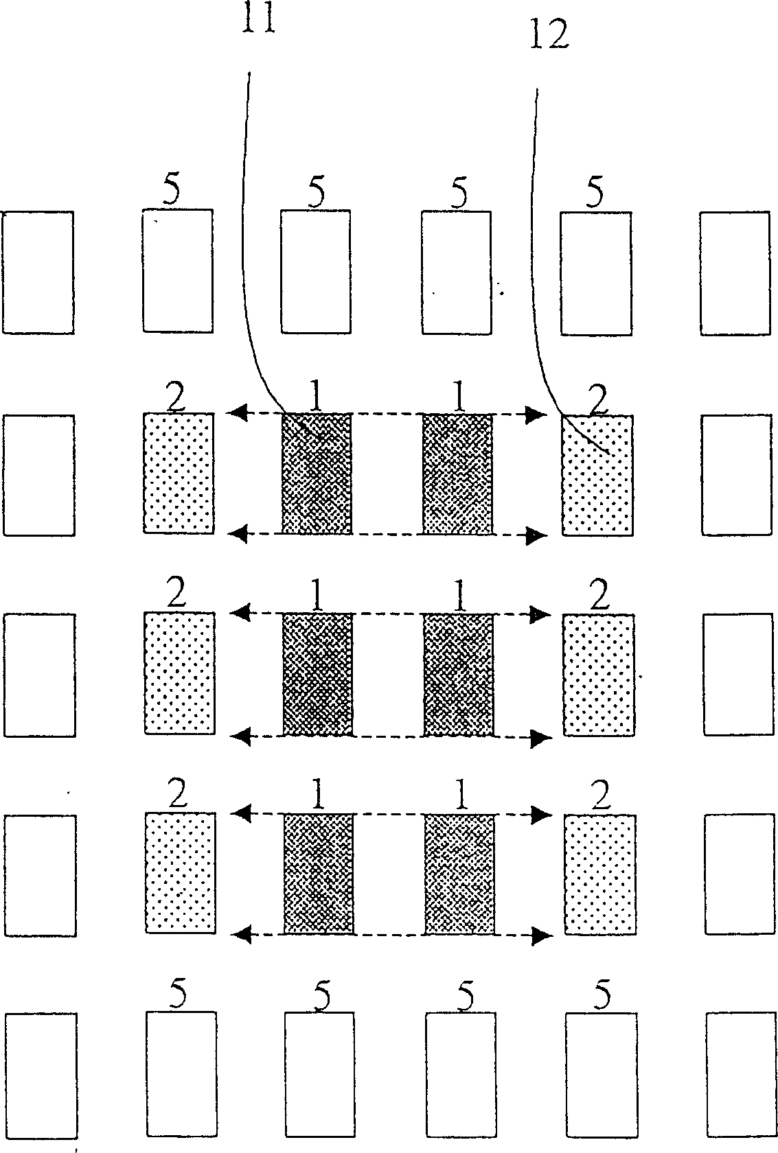
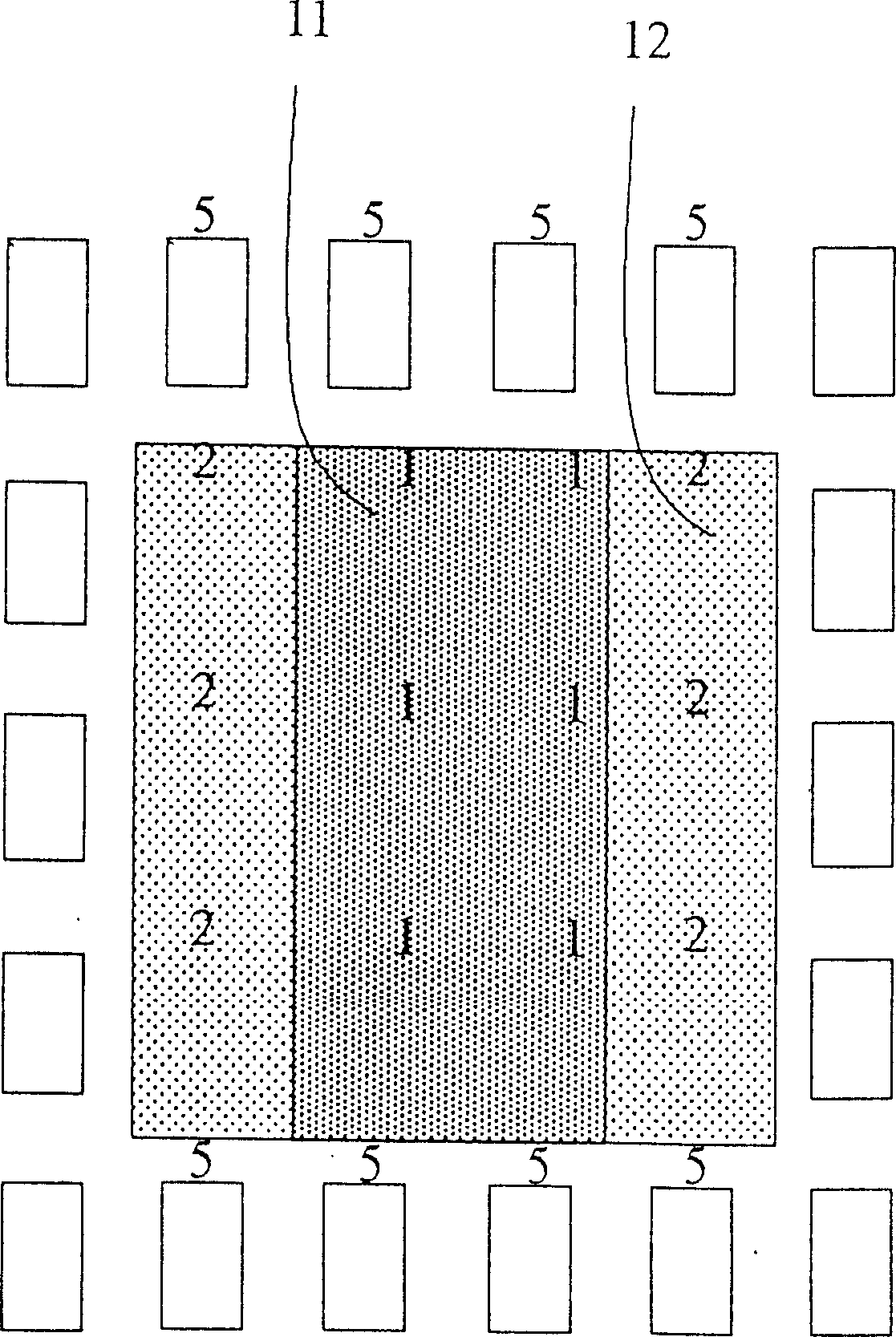
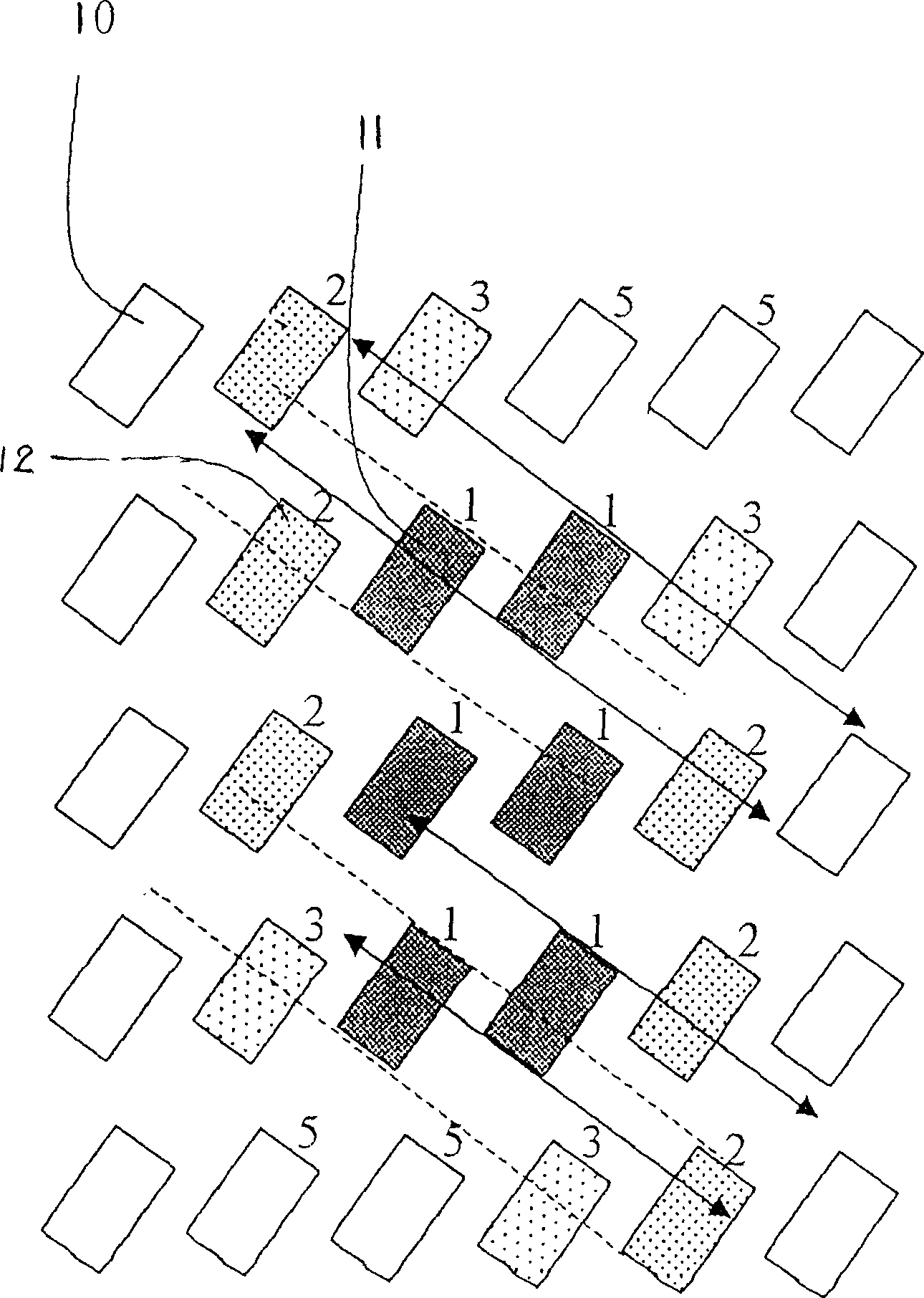
[0023] image 3 It is a schematic diagram of the first embodiment of the present invention. In this embodiment, the LED display units 10 are arranged in 5 rows and 6 columns, and the long side of each display unit is deflected 45° to the right relative to the reference coordinate axis Y. In the figure, the display unit 11 with 3 rows and 2 columns in the center of the display is the brightest area when the display panel is working, and displays the required image, which is visually displayed as the image of the number 1. Since the long side of each display unit is deflected relative to the reference coordinate axis Y-axis, the diffuse light of the long side of the display unit 11 in the brightest area is as follows: image 3 As shown by the arrow in , it deflects at the same angle as the above-mentioned deflection angle with respect to the Y axis, and spreads obliquely to both sides. 12 receives the diffused light from the display unit 11, and its brightness is slightly lower...


PUM


Abstract

The LED display plate comprises the matrix of display units, whose long edge is deflected an angle in 30-60 degrees either right or left deflexion related to the reference coordinate axis. The said deflexion makes the light direction of diffusion generate the relevant deflextion angles so as to create the effect of vision fluctuation. Moreover, light-absorbing materials or reflective materials can be coated on the LED display units, making the LED display plate possess various effects of vision fluctuation. The invention generates virtual 3D vision effect without need of changing the display control program.

Description

Technical field [0001] The invention relates to an LED display board, in particular to an LED display board capable of producing virtual stereoscopic visual effects. Background technique [0002] Existing LED display panels such as figure 1 As shown, the display matrix is ​​composed of LED units arranged vertically and horizontally. Each LED unit 10 has two long sides and two short sides, which are respectively parallel to the reference coordinate axes Y axis and X axis (not shown in the figure). When the LED unit emits light, light will diffuse from the above-mentioned long side and short side. For the convenience of explanation, the present invention only uses the light diffusion of the long side for illustration. The direction of diffusion is shown by the horizontal arrow in the figure. Diffusion is relatively weak and is omitted here. [0003] figure 1 The brightness of the LED display unit in the middle is expressed by the density of spots marked on the display unit....

Claims


Application Information

Patent Timeline
Patent Type & Authority Applications(China)
IPC IPC(8): G02B27/22G02B27/28
Inventor 汪秉龙
Owner 汪秉龙
Why Eureka
Try Eureka