Punch

A technology of hole punch and hole shaft, which is applied in the field of hole punch, and can solve the problems of large-scale hole punch, weight increase, and heavier operating handle, etc.

Inactive Publication Date: 2004-01-14
KOKUYO CO LTD
View PDF0 Cites 6 Cited by
  • Summary
  • Abstract
  • Description
  • Claims
  • Application Information

AI Technical Summary

Problems solved by technology

In this regard, in order to reduce the operating force, it can also be considered to install a long operating lever, set a long length from the center of rotation to the point of action of the operating force, or increase the operating handle, etc., but if this structure is The problem of increasing the size and weight of the hole punch

Method used


Image

  • Punch
  • Punch
  • Punch

Examples


Embodiment Construction

[0024] Hereinafter, one embodiment of the present invention will be described with reference to the drawings.

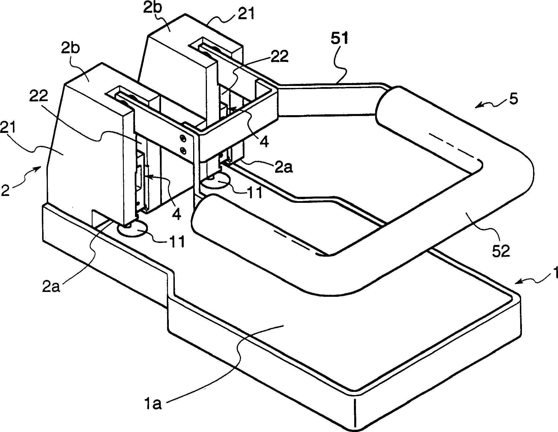
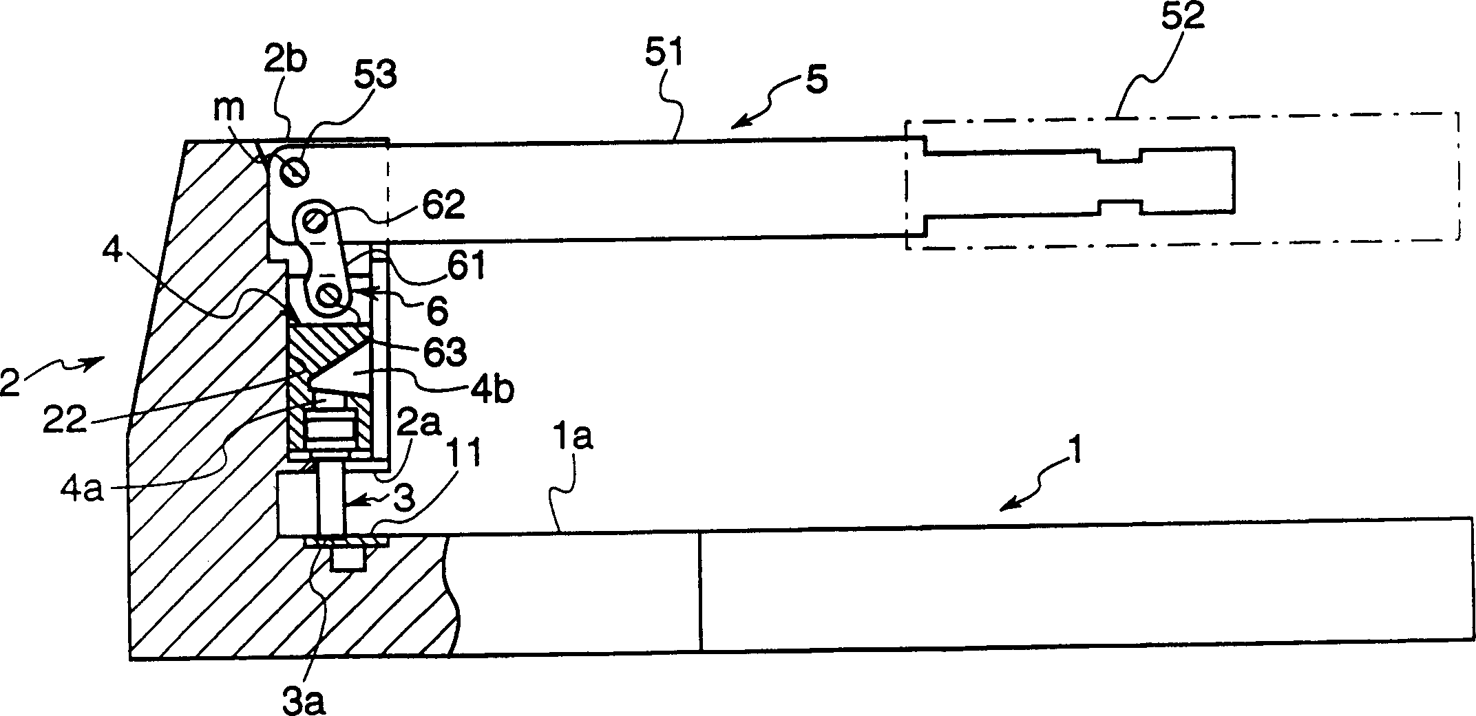
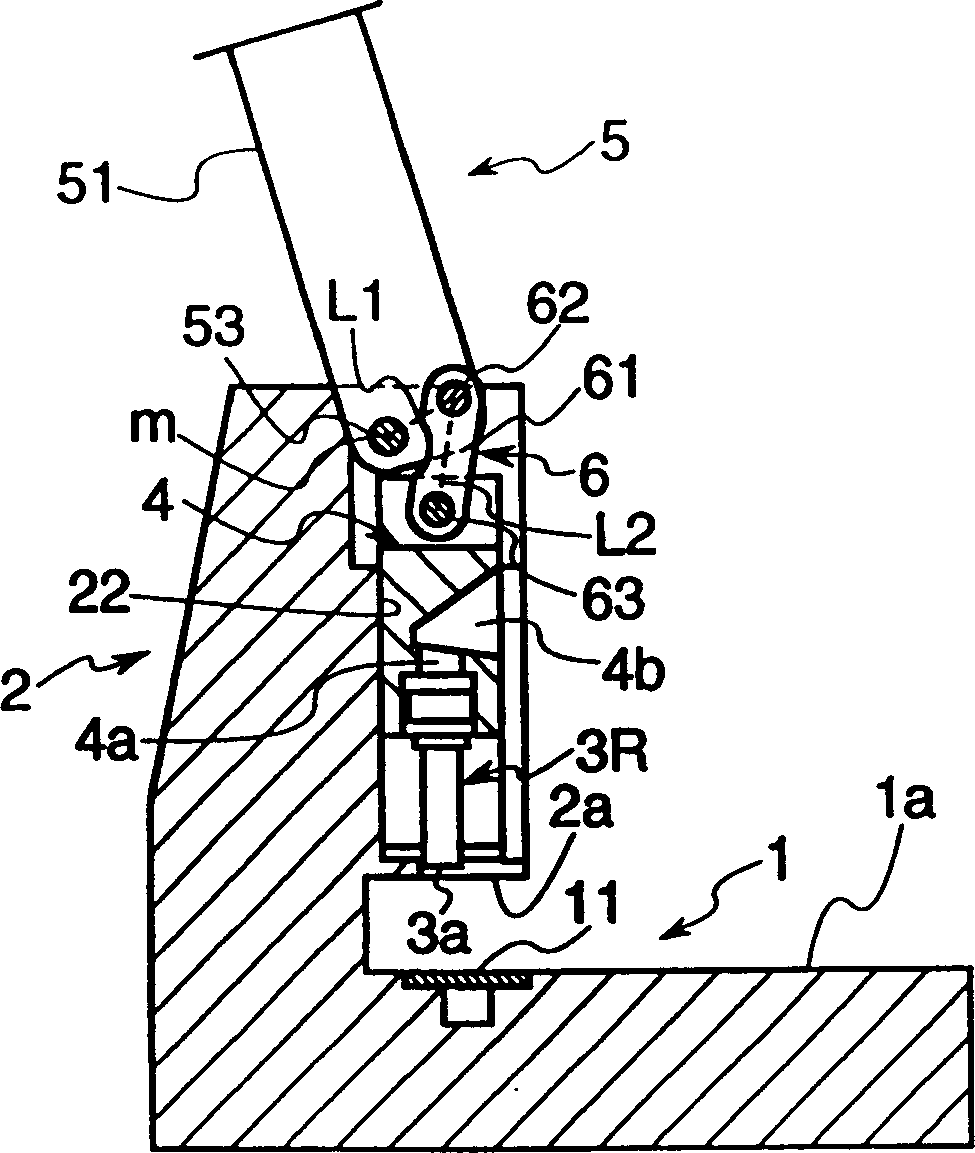
[0025] The puncher of this embodiment, as figure 1 as well as figure 2 As shown, it includes: a base 1; a holding member 2 integrally erected from one side of the upper end (the direction in which the paper is inserted) of the base 1; Pedestal 4; the base end side is rotatably supported on the upper end side of the above-mentioned holding member 2; 6.

[0026] The base 1 is a plate-shaped base with sufficient rigidity to support the operating handle 5 as the holding member 2 and its accessories. While the upper surface is used as the paper placement surface 1a, the punching shaft near its upper end 3, a resin circular spacer 11 that receives the tip 3a of the same punching shaft 3 is embedded in a state where its upper surface and the loading surface 1a are substantially the same.

[0027] The holding member 2 protrudes forward relative to the part contacting th...


PUM


Abstract

Provided is a punch wherein an operation force required for punching is effectively reduced with a simple constitution. This punch is equipped with two hollow-like punching shafts 3R, 3L, and perforation timings of the punching shafts 3R, 3L are mutually differentiated.

Description

technical field [0001] The present invention relates to a puncher for punching a plurality of sheets of paper, in particular to a puncher for reducing the punching operation force with a simple structure. Background technique [0002] Conventionally, for binding documents, there are known hole punches that make two or more holes along the edge of the binding side. For example, for a hole puncher used to make two holes on a file, a pair of punching shafts are installed at an installation position that deviates from the center of the rotation shaft of the operating handle that is installed as a rotatable base end. If the operating handle starts to operate When the position is rotated, the punching shaft will descend, and holes can be punched at the corresponding two positions of the file. [0003] Among them, the so-called powerful puncher is a puncher that can punch more than 100 sheets of paper. The punching shaft is hollow, and the cut chips are sequentially taken into the...

Claims


Application Information

Patent Timeline
Patent Type & Authority Applications(China)
IPC IPC(8): B26F1/32
Inventor 古川胜章
Owner KOKUYO CO LTD
Why Eureka
Try Eureka