Rotary switch operating mechanism

A technology of switch operation and operating mechanism, which is applied in the field of switches, can solve the problems of reducing operating force, reducing stability, reducing contact stability, etc., and achieves the effects of prolonging mechanical life, reducing strength requirements, and reducing operating force

Pending Publication Date: 2020-03-24
SHANGHAI LIANGXIN ELECTRICAL
View PDF1 Cites 3 Cited by
  • Summary
  • Abstract
  • Description
  • Claims
  • Application Information

AI Technical Summary

Problems solved by technology

But, because the pawl is released by the process of being blocked by the locking projection of the upper cover, the pawl is pressed by the protruding arm to retract to the long slot hole of the notch, and the power to drive the lever to rotate is along the circumference, pressing the pawl to retract The force is axial, so there is a large energy loss when the force input by the handle is converted into the force that presses the pawl to retract, and the amount of this loss depends on the retraction amount of the pawl, and the retraction amount is determined by the pawl and the pawl. The buckle amount of the locking protrusion protruding from the inner side of the upper cover is determined by the
In the case of a large energy loss, the switching operating mechanism must have a greater input of operating force, which requires each part to have greater strength to withstand the increased operating force, and at the same time greater operating force will cause Increased wear between parts, making the operating mechanism more susceptible to damage and failure
In order to reduce the operating force, the method of reducing the amount of buckle can be adopted, which will indeed reduce the energy loss, but the reduction of the amount of buckle will inevitably reduce the contact stability, especially after a certain amount of mechanical life is worn out, it is easier cause a decrease in stability

Method used


Image

  • Rotary switch operating mechanism
  • Rotary switch operating mechanism
  • Rotary switch operating mechanism

Examples


Embodiment

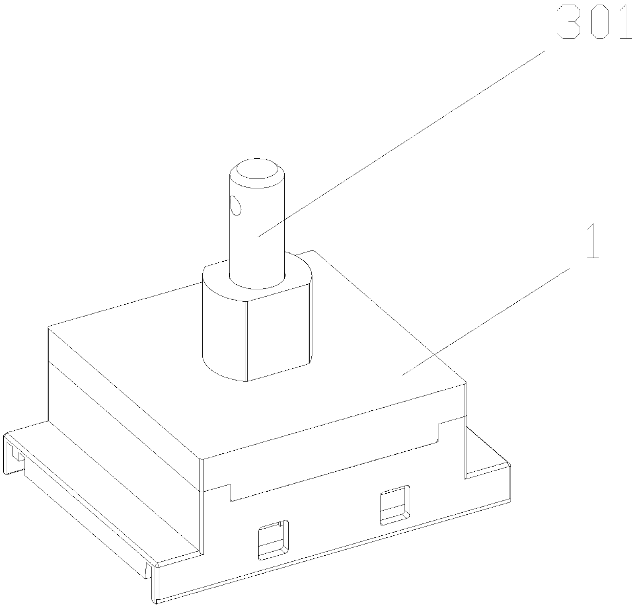
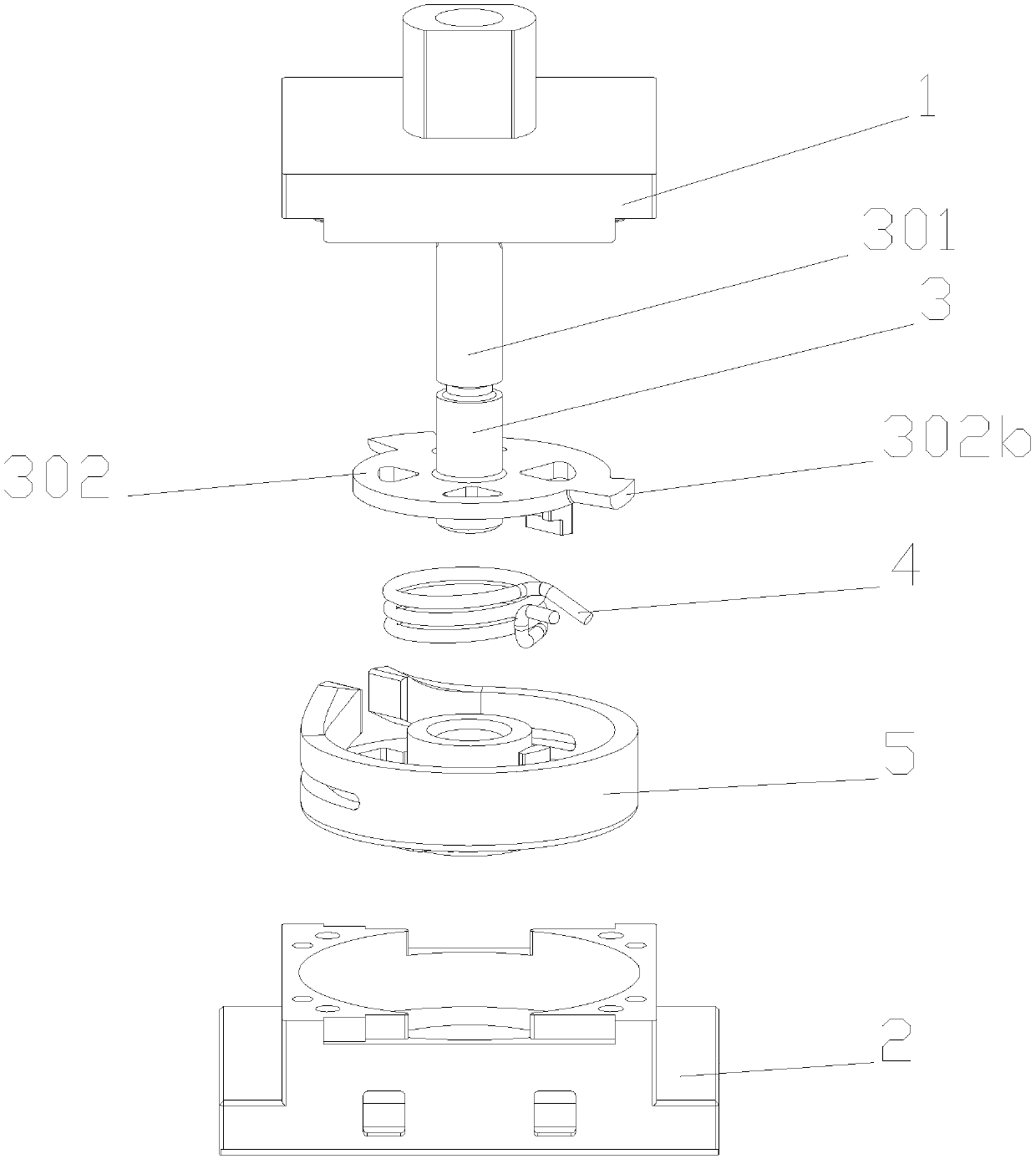
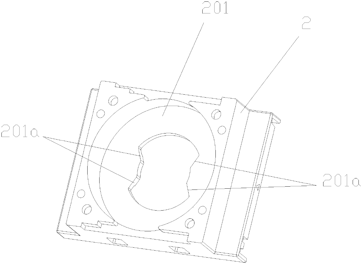
[0034] as attached figure 1 and 2 As shown, a rotary switch operating mechanism designed in this embodiment includes an upper cover 1, an installation base 2, a lever 3, an energy storage element 4 and a rotating shaft 5, and the rotating shaft 5 is installed in the attached image 3 The shaft installation groove 201 of the installation base 2 shown can be rotated in the shaft installation groove 201, the bottom of the rotation shaft 5 is provided with a stop protrusion 505, and the bottom surface of the shaft installation groove 201 of the installation base 2 is provided with a stopper The stopper 201a is installed in the rotating shaft installation groove 201 of the installation base 2 during the rotation process, the stop projection 505 can be limited by the stop stopper 201a to realize the stop of the operating mechanism. The energy storage element 4 is installed in the groove 501 of the inner cavity of the rotating shaft 5, and the end of the energy storage element 4 is ...


PUM


Abstract

A rotary switch operating mechanism is characterized in that the width of the end part of a pawl (502a) arranged on a rotating shaft (5) of the operating mechanism is gradually changed, and is gradually increased from one end far away from the end surface (502a01) of the pawl (502a) to the end surface (502a01) of the pawl (502a). According to the improved structure of the rotary switch operating mechanism, the pawl is arranged in a gradual change form, and the width of the end part of the pawl is increased from narrow to wide, so that the width of the hasp is increased, the height of the haspcan be properly reduced, the total hasp area is not changed, and the stability and the reliability are not reduced. The structure with the pawl width gradually changing only exists on the guide inclined face, the rigidity of the pawl cannot be increased, and in other words, the operation force value needed by the same retraction amount generated when the protruding arm presses the pawl cannot be increased. And after the height of the hasp is reduced, the required operating force is reduced, the strength requirement on each part is also reduced, the abrasion is reduced, and the mechanical service life of the operating mechanism is prolonged.

Description

technical field [0001] The invention belongs to the technical field of switches, and in particular relates to a rotary switch operating mechanism. Background technique [0002] The word switch is interpreted as on and off. It refers to a component that can open a circuit, interrupt the current flow, or cause it to flow to other circuits. The most common switches are human-operated electromechanical devices that have one or more contacts. The "closed" of the contact means that the contact is conducting and allows the current to flow; the "open" of the switch means that the contact is not conducting and forms an open circuit, and the current is not allowed to flow. The development history of the switch has developed from the original switch that requires manual operation to the intelligent switch used in various large-scale electrical control equipment. The function of the switch is more and more, and the safety is getting higher and higher. A rotary switch is a common swit...

Claims


Application Information

Patent Timeline
Patent Type & Authority Applications(China)
IPC IPC(8): H01H3/46H01H3/38H01H19/14
CPCH01H3/38H01H3/46H01H19/14
Inventor 施健张广智施巍李惠敏
Owner SHANGHAI LIANGXIN ELECTRICAL
Why Eureka
Try Eureka