Al technical title is built by PatSnap Al team. It summarizes the technical point description of the patent document.
A high-voltage DC, contactor technology, applied in relays, electrodeless relays, electromagnetic relays, etc., can solve the problems of low protection level, no self-cleaning ability of contacts, complex structure, etc. The effect of gate triggering time and simple contact structure
Active Publication Date: 2012-05-02
武汉长海电气科技开发有限公司
View PDF4 Cites 8 Cited by
Summary
Abstract
Description
Claims
Application Information
AI Technical Summary
This helps you quickly interpret patents by identifying the three key elements:
Problems solved by technology
Method used
Benefits of technology
Problems solved by technology
Traditional electromagnetic contactor contacts generally do not have arcing contacts, and it is difficult to achieve both breaking capacity and electrical life of the contacts; since there is no commutation and arcing channel, the contacts are severely burned during the breaking process; arc extinguishing Most of the chambers adopt metal grid structure, which leads to high breaking overvoltage and poor heat dissipation, which is not suitable for frequent operations greater than the rated current; moreover, the contacts have no self-cleaning ability, and dust and small debris are easy to remain on the contact surface and burn marks , resulting in a substantial increase in the contact pressure drop of the circuit; the reaction force of the breaking action is mostly provided by a tension spring plus a lever mechanism, which takes up a large space and is difficult to install and adjust; the U-shaped choke iron is placed vertically, and the magnetic circuit is not well sealed, resulting in The magnetic force is lost, dust and sundries are easy to enter, and the protection level is low; the bushing is made of copper-based material, and the mechanical life is short; the arc blowing device uses a permanent magnet device, which is not conducive to non-polar current breaking, and the structure is complex, takes up a lot of space, and is difficult to install Big
Method used
Image
Click on the blue label to locate the original text in one second.
Reading with bidirectional positioning of images and text.
Examples
Embodiment Construction
[0031] The present invention is further described as follows in conjunction with accompanying drawing and embodiment:
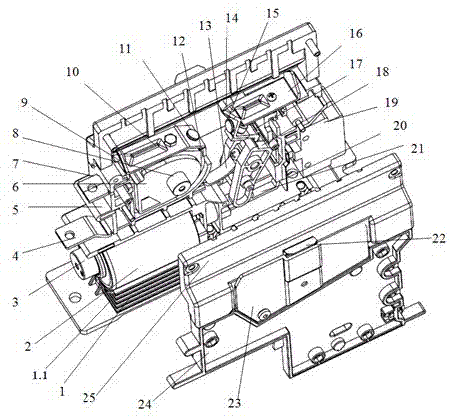
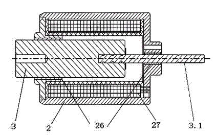
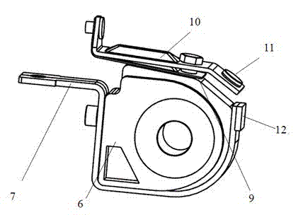
[0032] Such as Figure 1 ~ Figure 4 Shown: a high-voltage DC contactor, which has an organic body part, an electromagnetic drive part, a transmission part and a magnetic blow part, as well as auxiliary contacts 19, and an arc extinguishing chamber 25; wherein: the body part has a base 1, a main frame 5, The main frame cover plate 24, the dynamic arc striking angle 16 installed on the main frame 5 and the lower connecting copper bar 4; the main frame 5 is the positioning reference of the entire contactor transmission part, and the main frame cover plate 24 is inlaid and assembled to form a body part; the electromagnetic driving part has a cylindrical yoke 2, a moving iron core 3 and a coil 27; the electromagnetic driving part is installed horizontally on the base 1 provided with a cooling fin 1.1; the transmission part has a pusher connected with the moving ir...
PUM
Abstract
The invention relates to a high-voltage direct-current contactor which is suitable for medium load systems in electrical power, metallurgy, mines, petroleum, traffic transportation and the like, and is especially suitable for a capacitor charging loop on an electric locomotive converter. The high-voltage direct-current contactor comprises an engine part, an electromagnetic drive part, a transmission part, a magnetic blow-out part, an auxiliary contact and an arc extinguish chamber, wherein the engine part is provided with a base, a main frame and a main frame cover plate; the transmission part is provide with a push rod, a reset spring, a rotary rack, a moving main contact and a moving arc contact; the electromagnetic drive part is provided with a cylindrical yoke, a movable iron core and a coil, and a lining is arranged between the cylindrical yoke and the movable iron core; and the magnetic blow-out part is provided with an iron core, a magnetic conducting iron plate, a magnetic blow-out coil, a static arc contact, an upper connecting copper bar and a static main contact. The high-voltage direct-current contactor has the advantages of long electric service life, high breaking speed, strong shock resistance capacity, compact structure, small volume, good tightness and the like, and is convenient in assembly and maintenance.
Description
technical field [0001] The invention relates to a high-voltage DC contactor, especially a high-voltage and small-capacity DC electromagnetic contactor, which is suitable for medium-load systems such as electric power, metallurgy, mining, petroleum, and transportation, and is especially suitable for capacitors on converters of electric locomotives. in the charging circuit. Background technique [0002] At present, the DC contactors used on new electric locomotives in my country mainly use electromagnetic force as the power source. Traditional electromagnetic contactor contacts generally do not have arcing contacts, and it is difficult to achieve both breaking capacity and electrical life of the contacts; since there is no commutation and arcing channel, the contacts are severely burned during the breaking process; arc extinguishing Most of the chambers adopt metal grid structure, which leads to high breaking overvoltage and poor heat dissipation, which is not suitable for fr...
Claims
Application Information
Patent Timeline
Application Date:The date an application was filed.
Publication Date:The date a patent or application was officially published.
First Publication Date:The earliest publication date of a patent with the same application number.
Issue Date:Publication date of the patent grant document.
PCT Entry Date:The Entry date of PCT National Phase.
Estimated Expiry Date:The statutory expiry date of a patent right according to the Patent Law, and it is the longest term of protection that the patent right can achieve without the termination of the patent right due to other reasons(Term extension factor has been taken into account ).
Invalid Date:Actual expiry date is based on effective date or publication date of legal transaction data of invalid patent.