

Transfix component having fluorosilicone outer layer
- Summary
- Abstract
- Description
- Claims
- Application Information
AI Technical Summary
Benefits of technology
Problems solved by technology
Method used
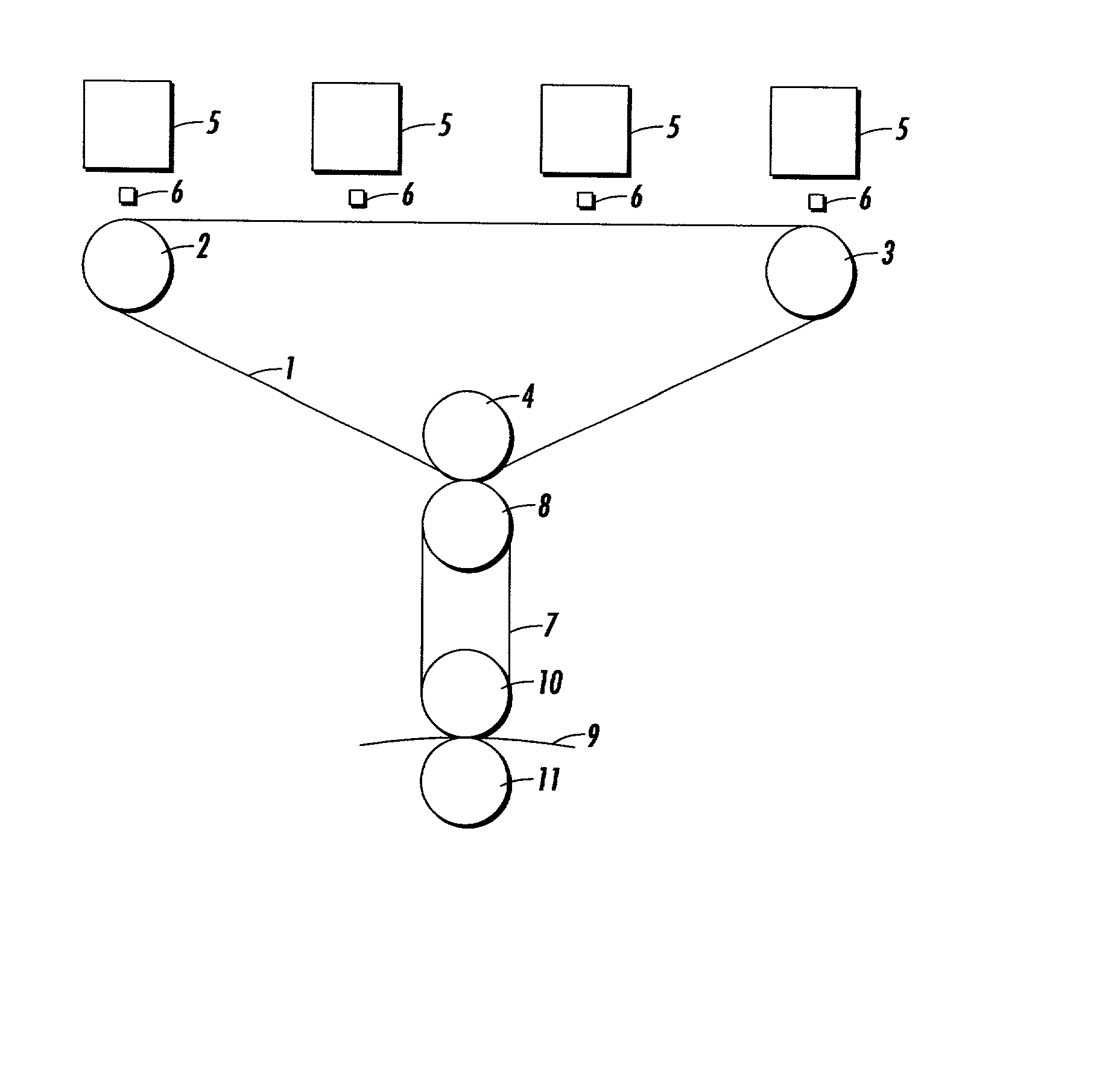
Image


Examples
example 1
[0059] Preparation of Fluorosilicone Outer Layer on Metal Belt with Volume Graft Intermediate Layer
[0060] Polyimide substrates (thickness about 3 mils), filled with indium tin oxide, having resistivity of about 10.sup.-10 ohms / sq were obtained from E.I. DuPont de Nemours & Company and were tape seamed into a belt shape. General Electric Co. adhesive GE2872-074 was then applied to a thickness of 0.2 to 0.3 mil (approximately 5 to 7.5 micrometers), air dried at ambient conditions for 30 minutes and baked at 150.degree. C. for 30 minutes.
[0061] Subsequently, the primed belts were provided with a coating of a Volume Graft elastomer which was prepared by dissolving 250 grams of VITON GF.RTM. in 2.5 liters of methylethyl ketone (MEK) by stirring at room temperature for 1 to 2 hours. The above solution was then transferred to a 5 liter Erlenmeyer flask and 25 milliliters of the amine dehydrofluorinating agent (3-(N-strylmethyl-2-aminoethylamino) propyltrimethoxysilane hydrochloride, S-1590...
example 2
[0065] Preparation of Fluorosilicone Outer Layer on Metal Belt with Fluoroelastomer Intermediate Layer
[0066] A belt having a stainless steel substrate, an intermediate layer comprising a fluoroelastomer, and an overcoat of fluorosilicone was prepared as follows. A solution of a flurooelastomer (VITON B50.RTM.) was prepared by dissolving 500 grams of the B50 in 5 liters of methylethyl ketone (MEK) and stirred at room temperature, about 25.degree. C. The following were added to 5 liters of this solution: 4.4 grams of magnesium oxide, 2.2 grams of calcium hydroxide, 11 grams of E.I. DuPont Curative VC50.RTM., and 10 grams of carbon black N991 obtained from Vanderbilt Corporation. The contents of the vessel were ball milled with media for 17 hours. The resulting black dispersion containing the VITON.RTM. B50 was then spray coated to a dry thickness of about 6 mils onto a stainless steel belt (thickness about 3 mils).
[0067] To the above belts, a top coat of fluorosilicone polymer was fab...
example 3
[0068] Preparation of Fluorosilicone Outer Layer on Metal Belt
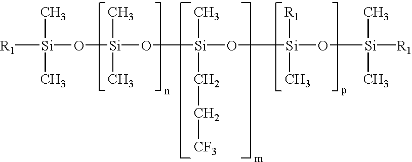
[0069] A stainless steel belt was primed with General Electric adhesive GE-2872-074 and an overcoat of fluorosilicone polymer was fabricated by the following techniques. Fluorosilicone LSR kit, Q5-8601 was obtained from Dow Corning Co., having a chemical formula believed to be encompassed by the general fluorosilicone structure disclosed herein. The kit contained fluorosilicone LSR, in two parts, part A and Part B. Both part A and B were added to 2000 grams of methyl isobutyl ketone in a ball jar containing ceramic media followed by ball milling for 1 hour. The resulting dispersion was then spray coated on the above belt to a dry thickness of 6 mils. The fluorosilicone overcoat was then cured in ambient dry air for 24 hours followed by heating at 110.degree. C. The resulting belt was comprised of stainless steel as substrate and fluorosilicone as an overcoat.
PUM
 Abstract
Description
Claims
Application Information