


Quick Research
Generate reliable direction feasibility study reports for your R&D in just a few steps.

Technical Q&A
Discover and master advanced knowledge NOW. Basics, ideas, possibilities, all at once.

Find Solutions
As an expert in R&D theories, this can generate solutions to your technical problems instantly.

Evaluate Feasibility
Analyze your overall solution with one click, know your potential R&D risks in advance.

Monitor Landscape
Get weekly tech updates, stay abreast of the latest tech innovations and key insights.
Magnetron
A technology for magnetrons and antennas, applied in the field of magnetrons, can solve problems such as reducing the operating efficiency of magnetrons
- Summary
- Abstract
- Description
- Claims
- Application Information
AI Technical Summary
Problems solved by technology
Method used
Image

Examples
Embodiment Construction
[0017] Preferred embodiments of the present invention will now be described in detail with reference to the accompanying drawings, wherein like reference numerals represent like elements throughout.
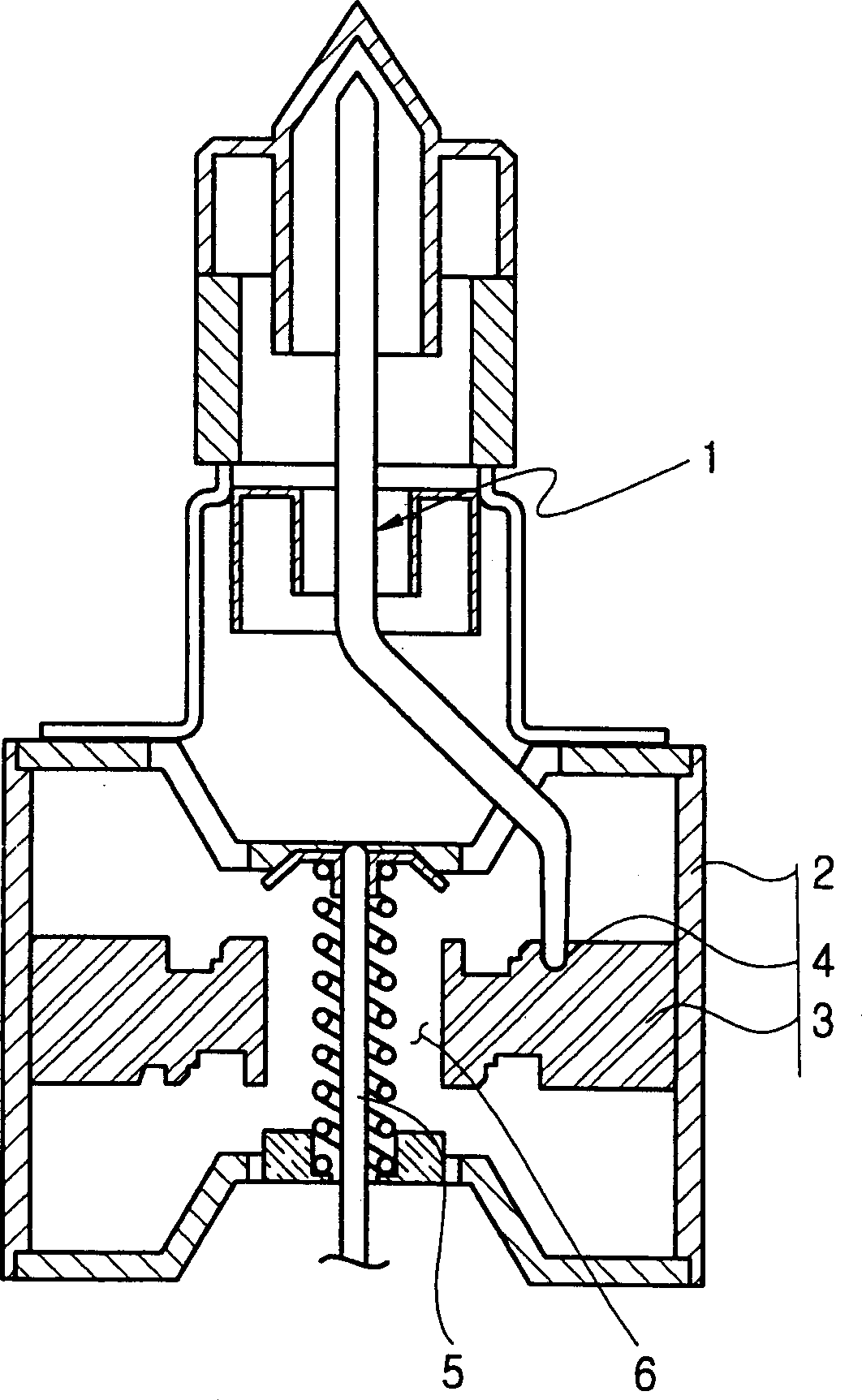
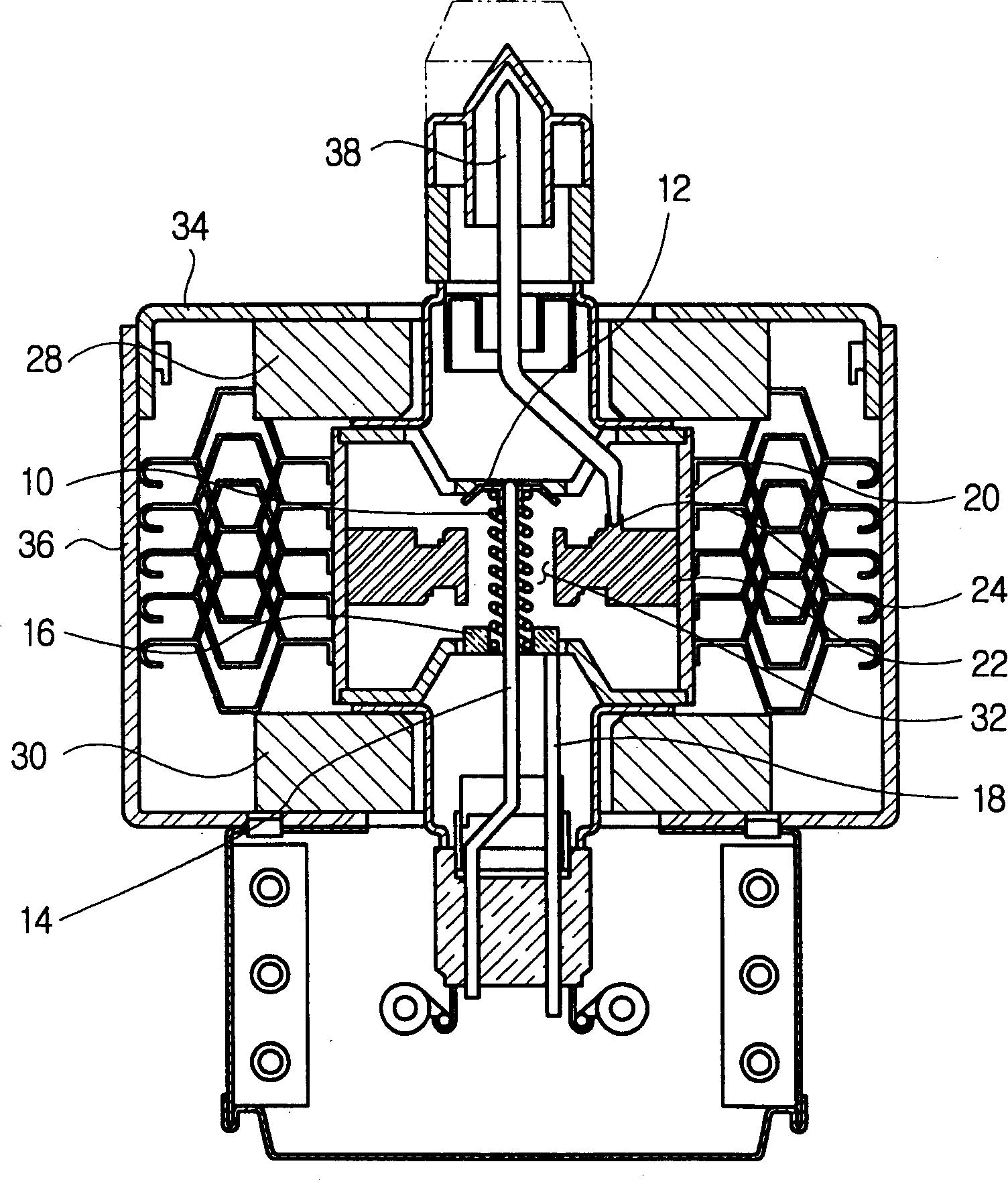
[0018] figure 2 is a sectional view showing the internal structure of a magnetron according to an embodiment of the present invention. Please refer to figure 2 , the cathode portion of the magnetron includes a filament 10 disposed along the central axis of the magnetron. Filament 10 is supported by central wire 14 and side wires 18 . A central lead 14 is connected to a first end of the filament 10 through an upper shield 12 and a side lead 18 is connected to a second end of the filament 10 through a lower shield 16 .
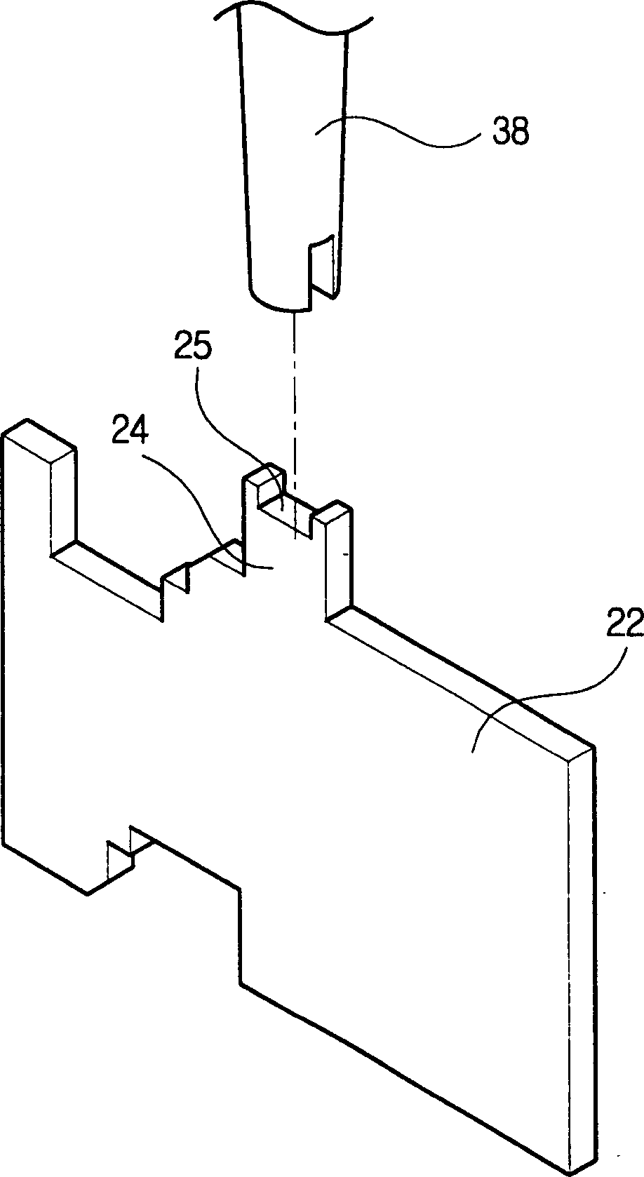
[0019] The anode portion of the magnetron includes an anode cylinder 20 and a plurality of wings 22 . The wings 22 project radially inwardly from the inner surface of the anode cylinder 20 such that the wings 22 are at a predetermined interval from the filame...
PUM
 Abstract
Description
Claims
Application Information
 - R&D Engineer
- R&D Manager
- IP Professional
- Industry Leading Data Capabilities
- Powerful AI technology
- Patent DNA Extraction
Browse by: Latest US Patents, China's latest patents, Technical Efficacy Thesaurus, Application Domain, Technology Topic, Popular Technical Reports.
© 2024 PatSnap. All rights reserved.Legal|Privacy policy|Modern Slavery Act Transparency Statement|Sitemap|About US| Contact US: help@patsnap.com