


Quick Research
Generate reliable direction feasibility study reports for your R&D in just a few steps.

Technical Q&A
Discover and master advanced knowledge NOW. Basics, ideas, possibilities, all at once.

Find Solutions
As an expert in R&D theories, this can generate solutions to your technical problems instantly.

Evaluate Feasibility
Analyze your overall solution with one click, know your potential R&D risks in advance.

Monitor Landscape
Get weekly tech updates, stay abreast of the latest tech innovations and key insights.
Stirling cylic engine
An engine and working gas technology, applied in the direction of machines/engines, gas cycle refrigerators, hot gas variable displacement engine devices, etc., can solve problems such as heat loss and performance reduction of Stirling cycle refrigerators
- Summary
- Abstract
- Description
- Claims
- Application Information
AI Technical Summary
Problems solved by technology
Method used
Image

Examples
no. 1 example
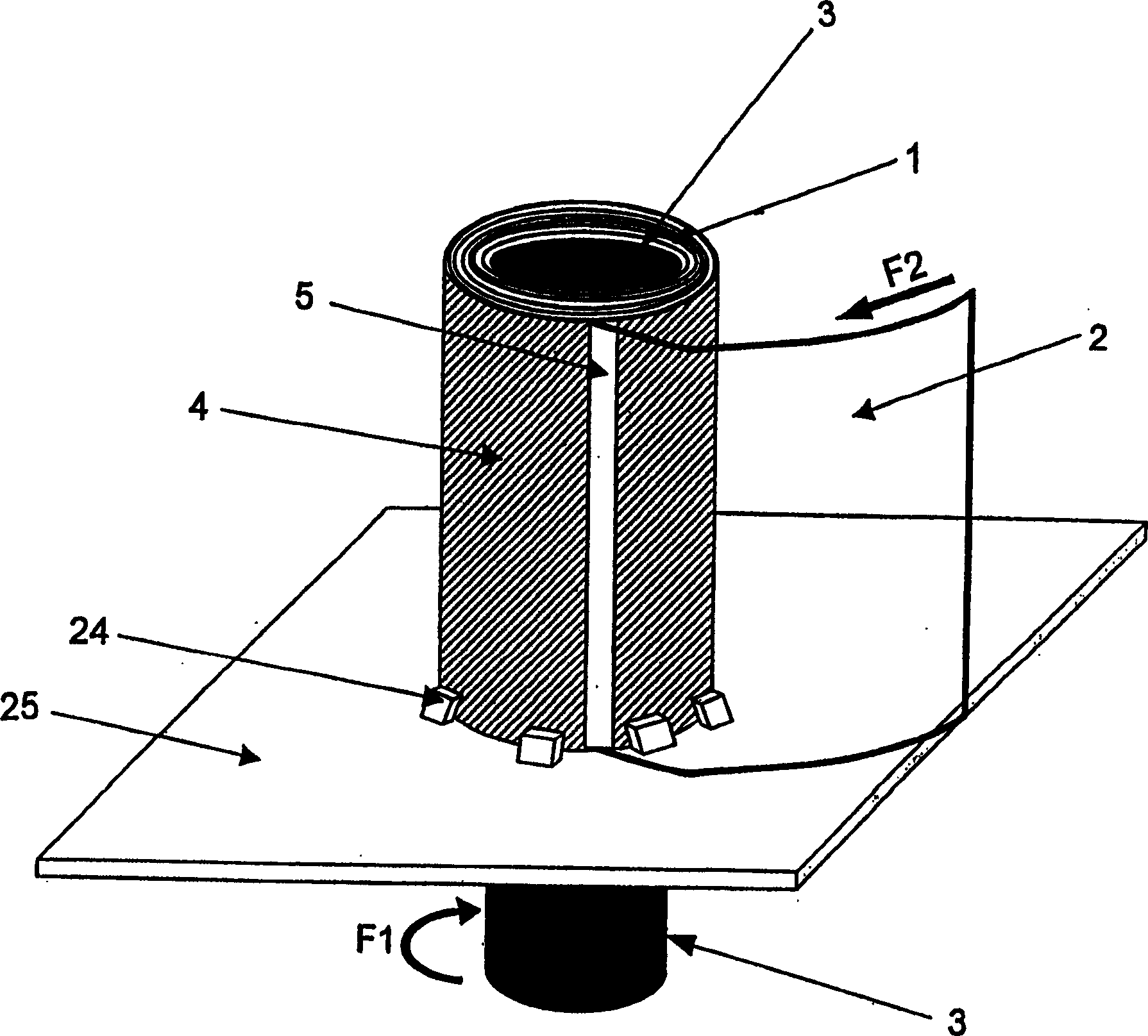
[0034] figure 1 is a perspective view showing the manufacturing process of the regenerator 1 used in the first embodiment of the present invention. A cylindrical bobbin 3 passes through a support stand 25, and a thin-walled cylindrical outer casing 4 having a diameter larger than the cylindrical bobbin 3 is mounted around the cylindrical bobbin 3. The thin-walled cylindrical casing 4 is fixed to a support stand 25 with stoppers 24 . The thin-walled cylindrical casing 4 has a slit 5 vertically formed therein.
[0035]Next, one end of the resin film 2 is inserted through the slit 5, fixed to the outer surface of the cylindrical bobbin 3, and then the cylindrical bobbin 3 is rotated in the direction indicated by the arrow F1, thereby further turning the cylindrical bobbin 3 as shown by the arrow F2. A resin film is inserted through the slit 5 and wound around the outer surface of the cylindrical bobbin 3 . When the thus wound resin film 2 reaches the inner surface of the thin...
no. 2 example
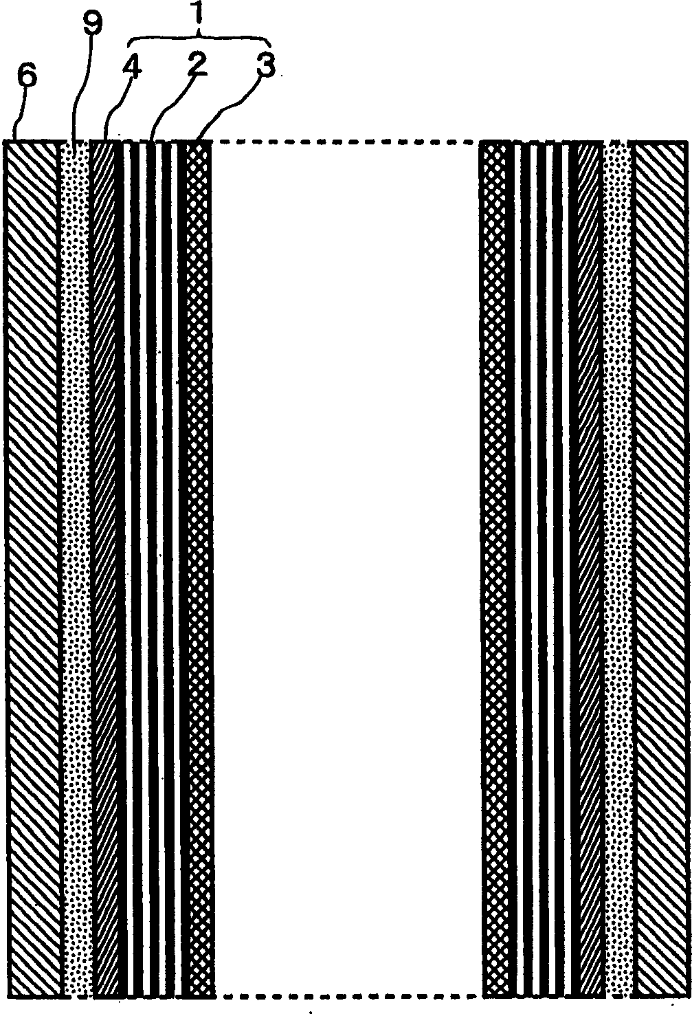
[0041] When the free-piston Stirling cycle engine is operating, compressed hot working gas and expanded cold working gas flow through the regenerator 1 in a reciprocating motion. At the same time, heat is exchanged between the resin film 2 and the working gas. Here, the heat of the working gas flowing close to the inner surface of the thin-walled cylindrical jacket 4 is dissipated by conduction to the cylinder 6 through the thin-walled cylindrical jacket 4 . This results in a loss of heat in the cylinder 6, thus reducing the performance of the regenerator.
[0042] In order to avoid this situation, in the second embodiment of the present invention, compared with the first embodiment, the thin-walled cylindrical jacket 4 is made of high heat insulating material. Examples of highly insulating materials include resins such as polycarbonate and ceramics.
[0043] In this structure, the heat of the working gas flowing through the regenerator 1 is blocked by the thin-walled cylind...
no. 3 example
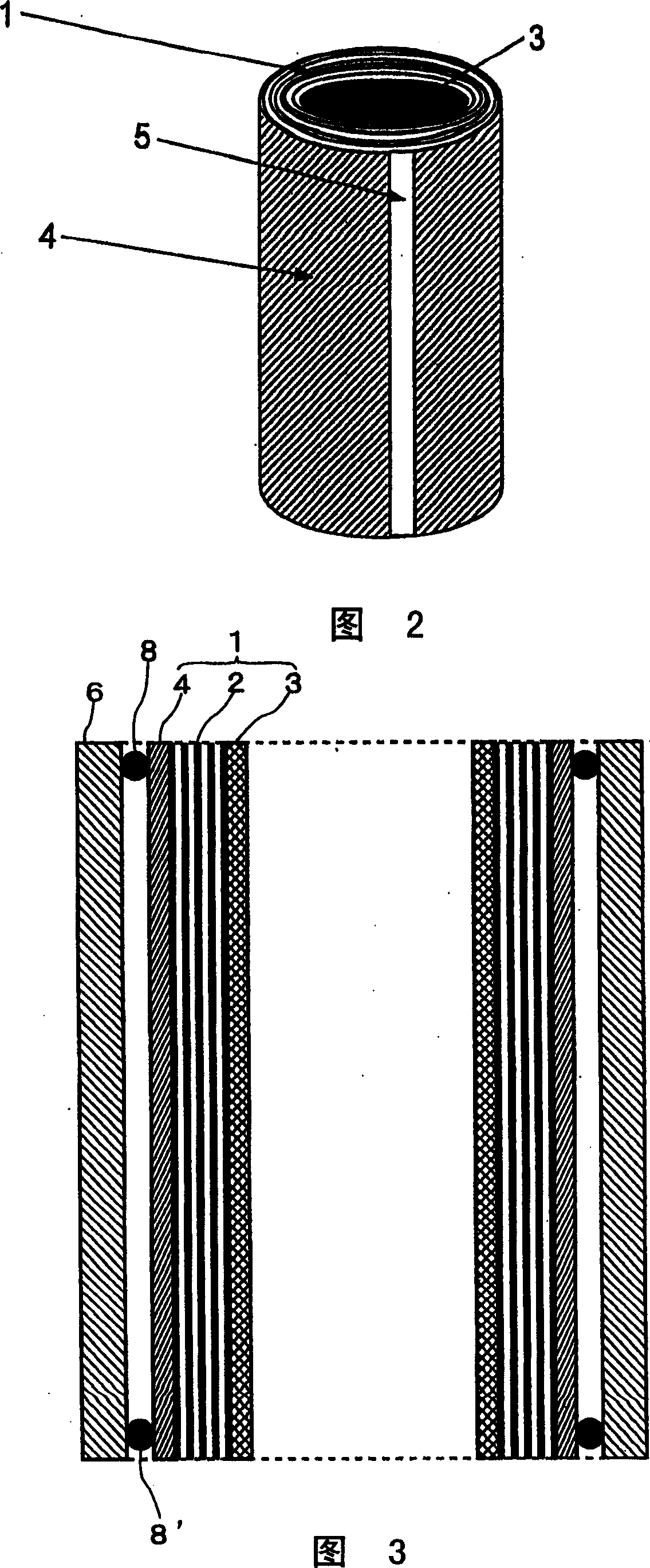
[0045] Fig. 3 is a side sectional view of a regenerator 1 used in a third embodiment of the present invention and parts surrounding it. Compared with the first embodiment, in the third embodiment, the outer surface surrounding the regenerator 1, that is, the outer surface surrounding the thin-walled cylindrical jacket 4, is equipped with O-rings 8 and 8' for sealing the thin-walled cylindrical The space between the outer cover 4 and the cylinder 6.
[0046] In this structure, the working gas is prevented from leaking between the thin-walled cylindrical jacket 4 and the inner surface of the cylinder 6 . In addition, a layer of air is formed between the thin-walled cylindrical casing 4 and the cylinder 6 by fitting O-rings 8 and 8' at both ends of the regenerator 1. This layer of air blocks the heat of the working gas so that it will not be dissipated due to conduction to the cylinder 6 through the thin-walled cylindrical jacket 4 . This increases the heat storage capacity of ...
PUM
 Abstract
Description
Claims
Application Information
 - R&D Engineer
- R&D Manager
- IP Professional
- Industry Leading Data Capabilities
- Powerful AI technology
- Patent DNA Extraction
Browse by: Latest US Patents, China's latest patents, Technical Efficacy Thesaurus, Application Domain, Technology Topic, Popular Technical Reports.
© 2024 PatSnap. All rights reserved.Legal|Privacy policy|Modern Slavery Act Transparency Statement|Sitemap|About US| Contact US: help@patsnap.com