
Method for reporting transmitting channel quality between transmitter and receiver

A transmission channel and transmitter technology, applied in the communication between multiple stations, transmission modification based on link quality, transmission system, etc., can solve the problem of increased packet error rate, increased interference level, and inability to correct transmission parameters, etc. question

Inactive Publication Date: 2004-03-10
MITSUBISHI ELECTRIC CORP
View PDF0 Cites 11 Cited by
  • Summary
  • Abstract
  • Description
  • Claims
  • Application Information

AI Technical Summary

Problems solved by technology

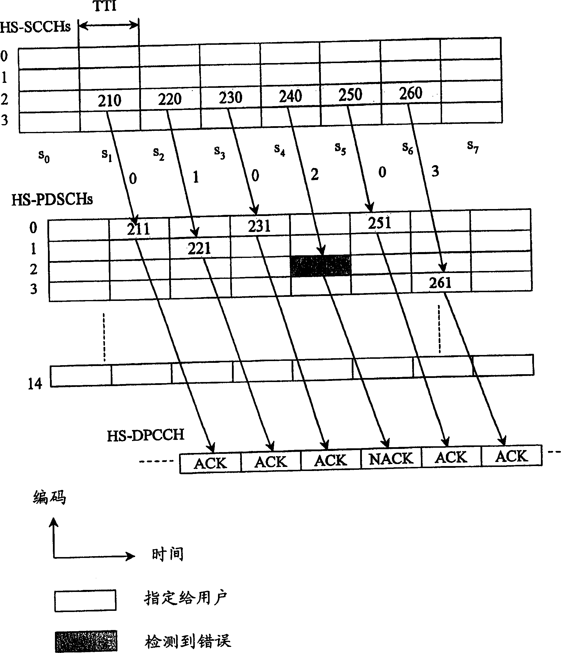
If the quality degrades between two scheduled CQI reporting times, the base station will not be able to modify the transmission parameters to cope with the poor transmission conditions, and thus the packet error rate will also increase
To mitigate this effect, a possible measure would be to adopt a shorter reporting period, however at the cost of a significant increase in the interference level on the uplink due to the more frequent transmission of CQI information
The reverse also happens when the quality of the transmission channel improves between two scheduled CQI report times: in this case the base station cannot benefit from the improved transmission conditions until the next report is received

Method used


Image

  • Method for reporting transmitting channel quality between transmitter and receiver
  • Method for reporting transmitting channel quality between transmitter and receiver
  • Method for reporting transmitting channel quality between transmitter and receiver

Examples


no. 1 example

[0021] Figure 5 Schematically represents the process of reporting channel quality information according to the first embodiment of the present invention;

[0022] Fig. 6 schematically shows the process of reporting channel quality information according to the second embodiment of the present invention.

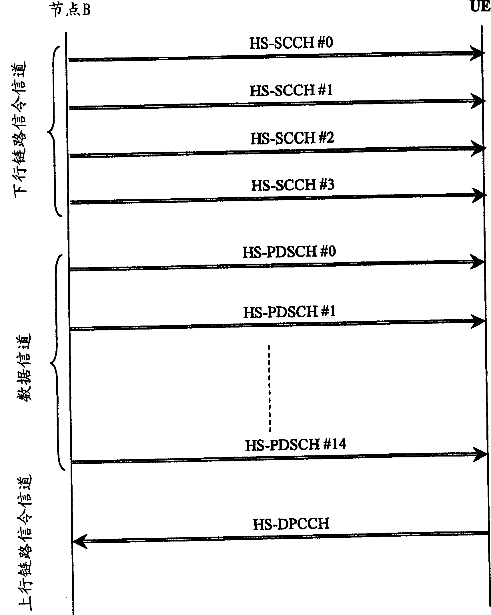
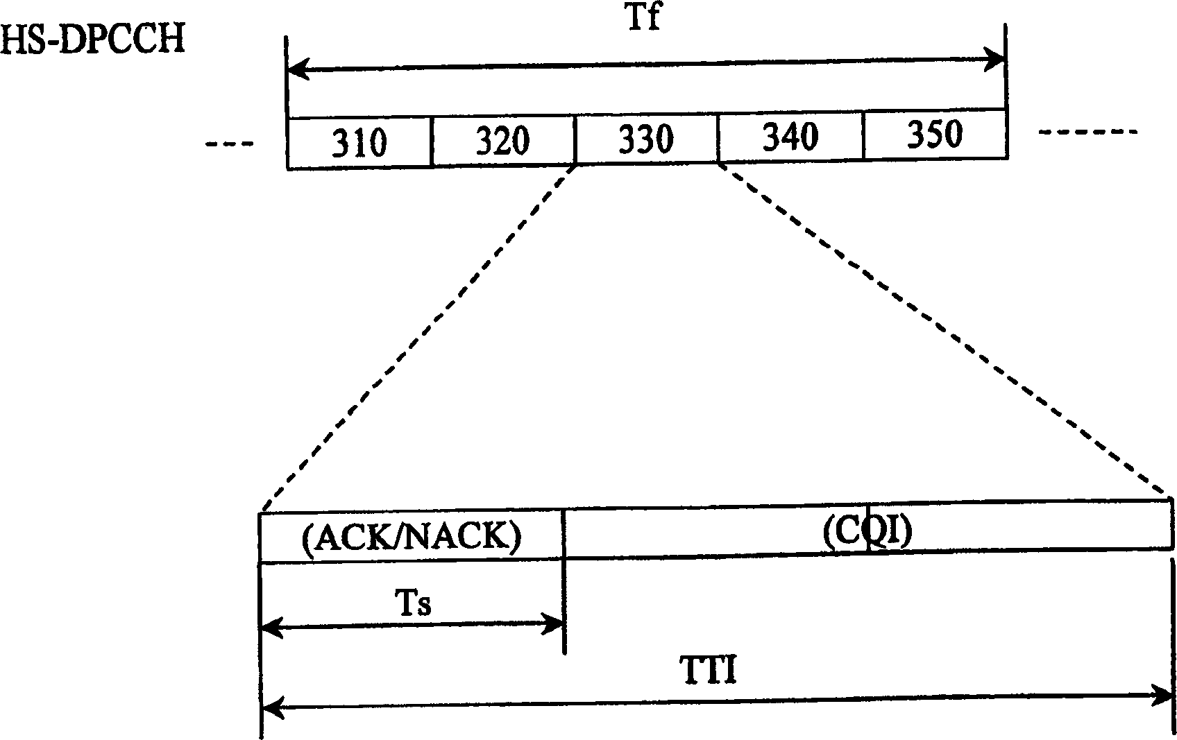
[0023] We still refer here to a telecommunication system in which: the sender (Node B) transmits a data subframe over a transport channel, and the receiver (UE) sends a negative acknowledgment (NACK) back to the subframe when it finds an error in the received subframe The sender sends an acknowledgment (ACK) when it finds that the received subframe has no errors. For example, the telecommunication system in question may be a UMTS telecommunication system in which mobile terminals are equipped with HSDPA access. It is also assumed below that the receiver reports information to the sender indicating its estimated transmission channel quality at a predetermined scheduled time....


PUM


Abstract

The invention concerns a method for reporting the quality of a transmission channel between a transmitter and a receiver, said transmitter transmitting frames of data over said transmission channel and said receiver sending back to said transmitter a non-acknowledgement information (NACK) when a received frame of data is detected as erroneous and said receiver sending to said transmitter at scheduled reporting times an information representative of the quality of the transmission channel at said reporting times. When the receiver sends a non-acknowledgement information back to said transmitter, it additionally sends an information representative of the quality of the transmission channel at the time the non-acknowledgement information is sent.

Description

technical field [0001] The invention relates to a method for reporting the quality of a transmission channel between a sender and a receiver. In particular, the present invention can be applied to mobile telecommunication systems supporting HSDPA. Background technique [0002] The use of High Speed ​​Downlink Packet Access (HSDPA) to enhance the Universal Mobile Telecommunications System (UMTS) has recently been proposed within the framework of the 3GPP Forum. The purpose of this new functionality is to enable fast access to packet services through a new transport channel called High Speed ​​Downlink Shared Channel HS-DSCH. The physical channel to which the HS-DSCH is mapped is also called HS-PDSCH (High Speed ​​Physical Downlink Shared Channel), and users can share this channel in the time domain or the coding domain. According to the user's needs, the user is allocated one or more channelization codes (or spreading codes) in the HS-DSCH. Furthermore, it is expected that...

Claims


Application Information

Patent Timeline
Patent Type & Authority Applications(China)
IPC IPC(8): H04L29/08H04B7/26H04L1/00H04L1/16H04L1/18
CPCH04L1/0027H04L1/0026H04L1/1819H04L1/1671
Inventor N·福奎
Owner MITSUBISHI ELECTRIC CORP
Learn More