Suitcase weighing method and self-weighing type suitcase thereof
A luggage and weighing technology, applied in weighing, measuring devices, instruments, etc., can solve the problems of inability to grasp the weight of the luggage, unable to control the weight, etc., and achieve the effect of simple structure, strong work reliability, and not easy to damage.
- Summary
- Abstract
- Description
- Claims
- Application Information
AI Technical Summary
Problems solved by technology
Method used
Image
Examples
Embodiment 1
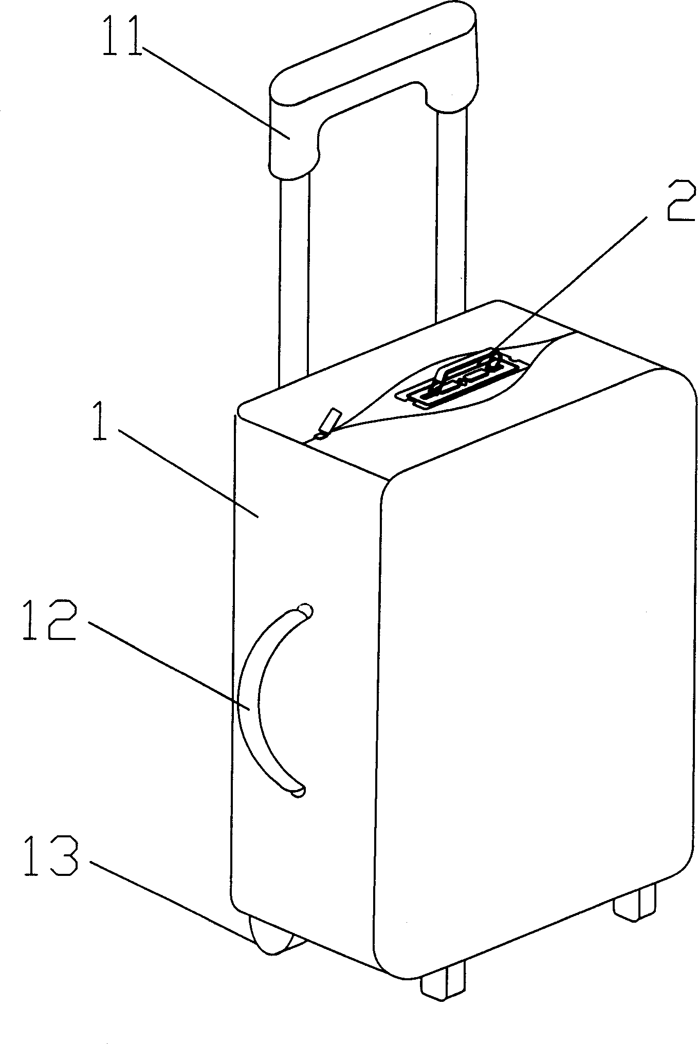
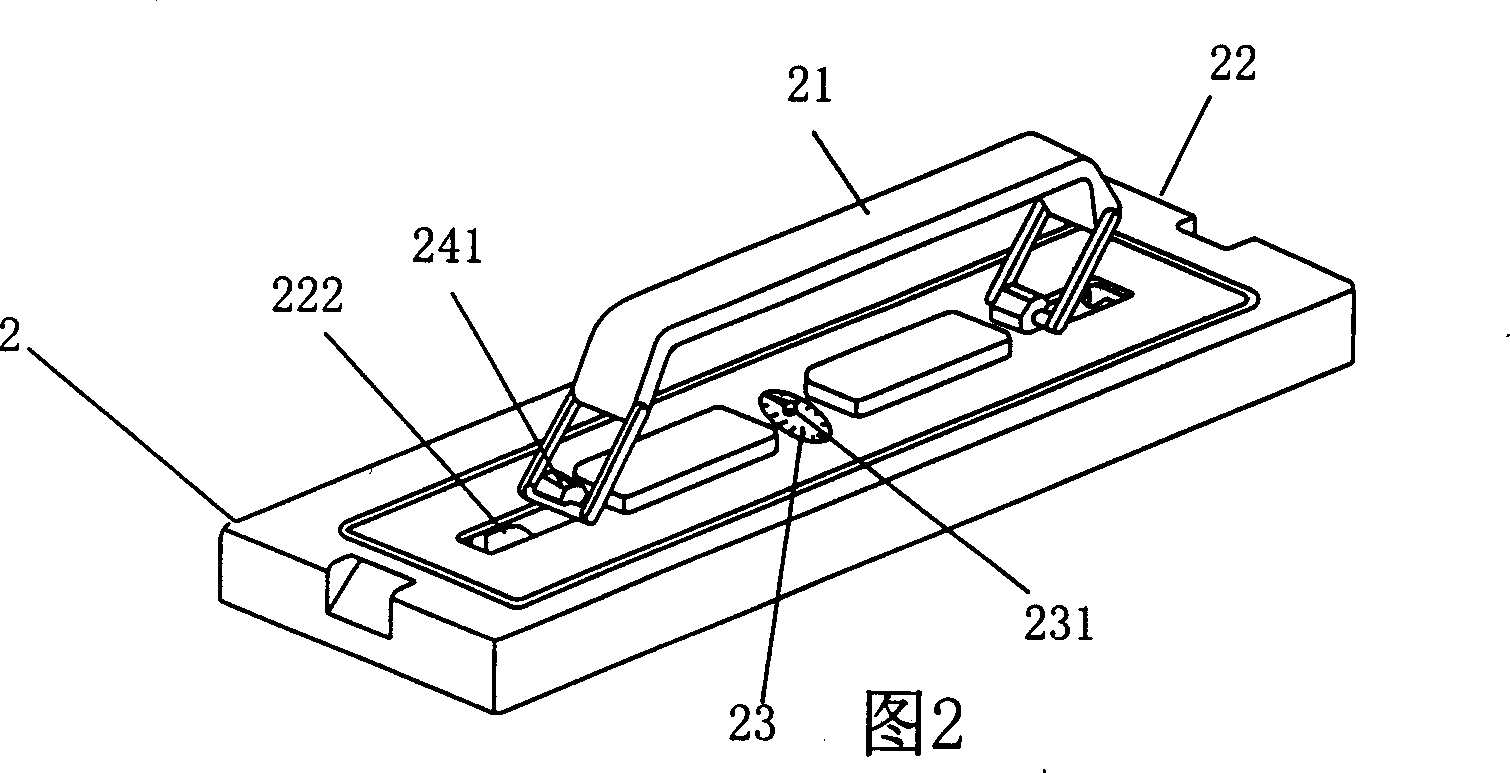
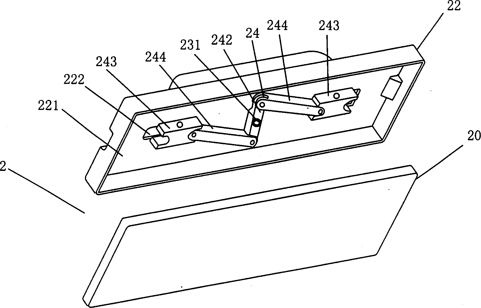
[0024] Embodiment 1, as attached figure 1 , Attached Figure 2, Attached image 3 As shown, a self-weighing suitcase of the present invention has a transmission mechanism of a crank connecting rod type, a pull rod group 11 is installed on the rear side of the box body 1, a roller 13 is installed at the bottom, and a suitcase handle is installed on one side. 12. A weighing device 2 is installed on the top of the box body 1, and an openable and closable zipper bag 12 is provided on the outside of the weighing device 2, and the periphery of the zipper bag 12 is sewn with the suitcase body 1 ;
[0025] Weighing device 2: composed of a handle 21, a fixed body 22, a weight indicator plate 23 with a pointer and a transmission mechanism 24. The fixed body 22 is fixedly connected with the casing 1 of the suitcase, and the transmission mechanism 24 is arranged in the cavity 221 of the fixed body 22, and the connectors 241 at both ends pass through the relief hole 222 of the fixed body ...
Embodiment 2
[0030] Embodiment two, such as Figure 4 , Figure 5 As shown, the present embodiment is a kind of self-weighing type suitcase, and its transmission mechanism is gear, rack type; It comprises two sliding parts 243, rotating part 242 and connecting part 241, and rotating part 242 is a gear, and one end of sliding part 243 A rack 2431 is provided, and the other end is fixedly connected with the connector 241, and the two sides of the end are provided with protrusions, which are placed and placed in the chute of the concave cavity 221 of the fixed body, and the racks 2431 of the two sliders 243 are respectively Placed on both sides of the gear 242 and meshed with the gear 242 , one end of the connecting piece 241 is fixedly connected with the sliding piece 23 , and the other end passes through the relief hole 222 of the fixed body 22 and is connected with the two connecting ends of the handle 21 with pivot pins.
[0031] Since the rotating part 242 structured as a gear meshes wi...
PUM
 Abstract
Description
Claims
Application Information
 - R&D
- Intellectual Property
- Life Sciences
- Materials
- Tech Scout
- Unparalleled Data Quality
- Higher Quality Content
- 60% Fewer Hallucinations
Browse by: Latest US Patents, China's latest patents, Technical Efficacy Thesaurus, Application Domain, Technology Topic, Popular Technical Reports.
© 2025 PatSnap. All rights reserved.Legal|Privacy policy|Modern Slavery Act Transparency Statement|Sitemap|About US| Contact US: help@patsnap.com


