Adjustable probe

A technology of trigger probe and measuring contact, which is applied in the direction of point coordinate measurement, measuring device, instrument, etc.

Inactive Publication Date: 2004-08-04
TESA SE
View PDF0 Cites 9 Cited by
  • Summary
  • Abstract
  • Description
  • Claims
  • Application Information

AI Technical Summary

Problems solved by technology

[0009] Another drawback of the described probe is that locking and unlocking requires an external torque to act on the locking wheel and be transmitted through the probe and its support to the moving arm of the measuring machine

Method used


Image

  • Adjustable probe
  • Adjustable probe
  • Adjustable probe

Examples


Embodiment Construction

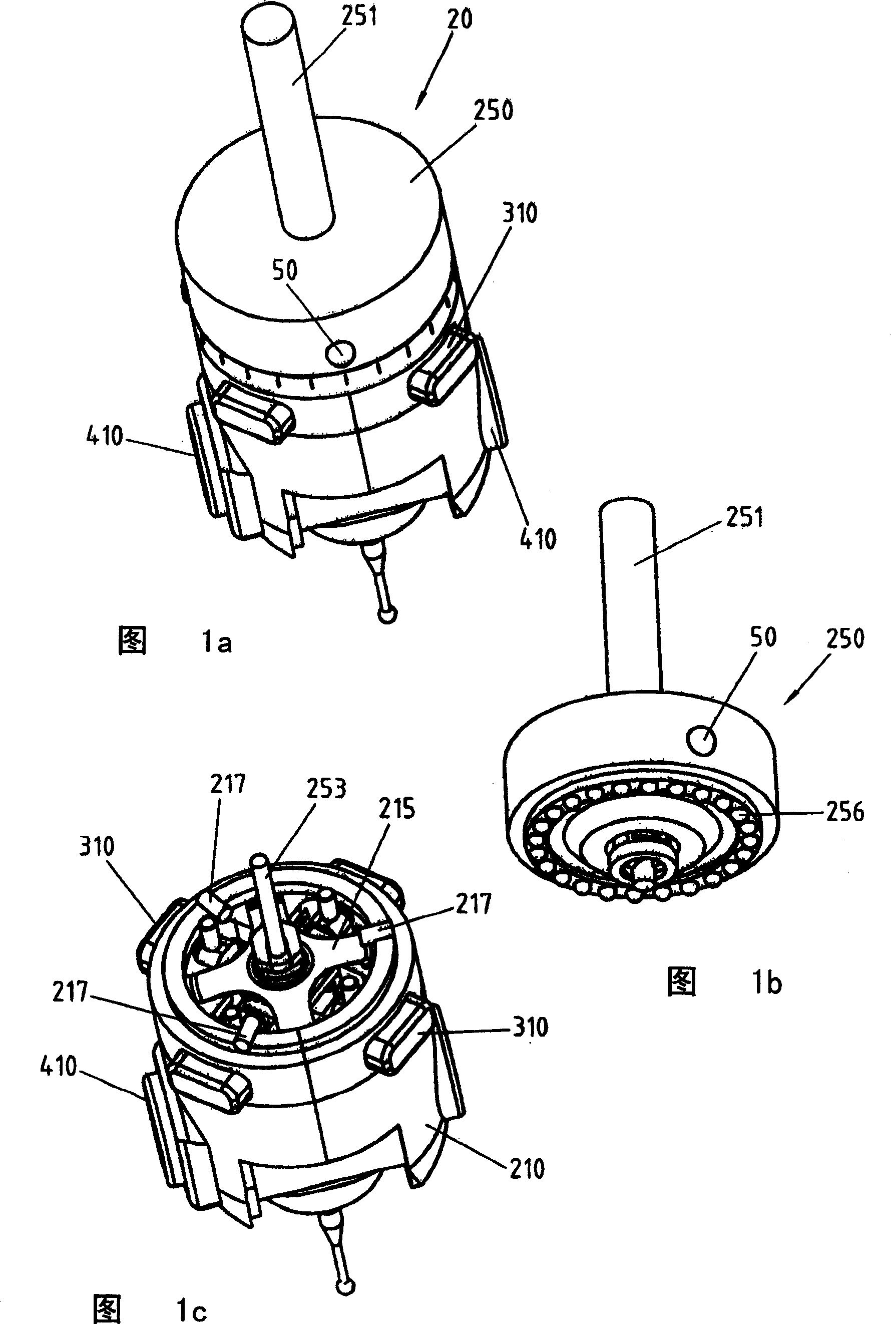
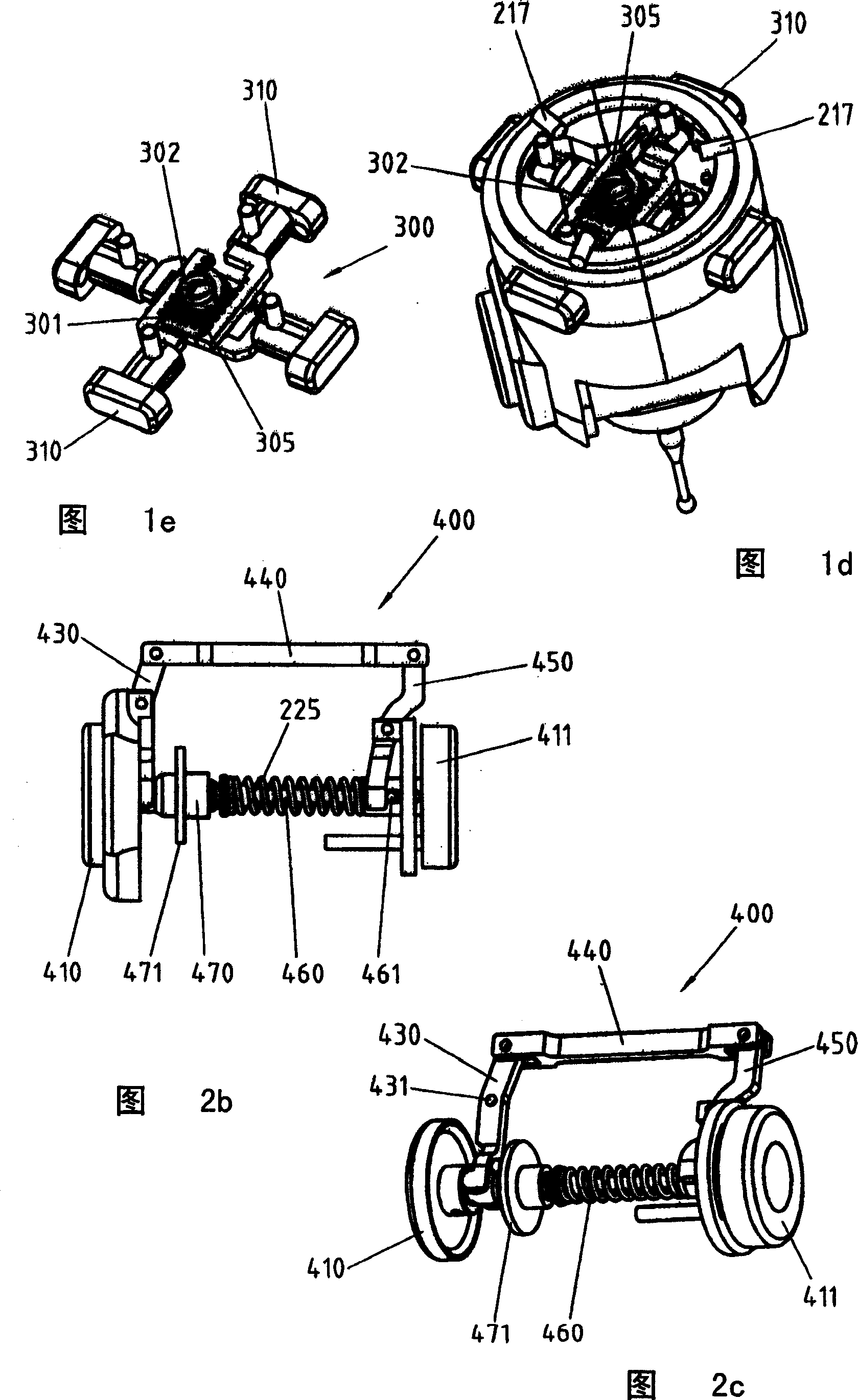
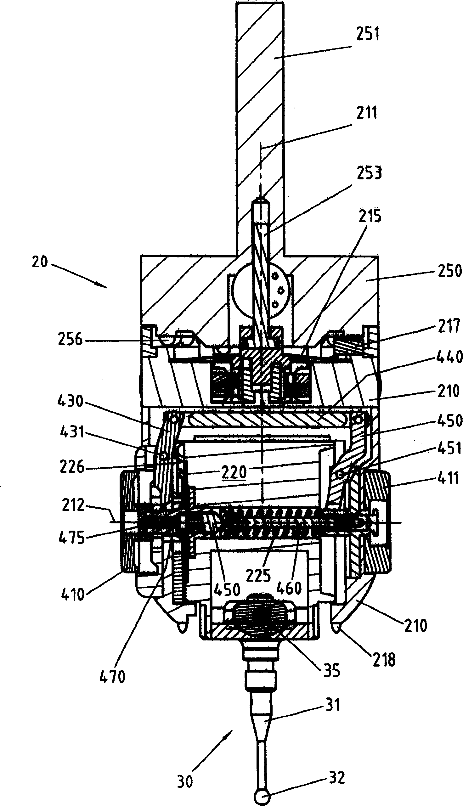
[0021] The first embodiment of the invention shown in Figures 1a-1e is a touch trigger probe 20 comprising a fixed part 250 shown in detail in Figure 1b, designed to be fastened by a threaded rod 251 or any other known fastening means On the moving arm of the measuring machine.

[0022] The fixing part 250 carries on its underside 24 balls 256 which are uniformly distributed in the circumferential direction and partly protrude downwards. Ball 256 defines 24 indexed positions spaced at 15 degree intervals about the first axis of rotation of the probe, as further described below. It is evident that different numbers of spheres can be used depending on the number of indexing positions required.

[0023] The moving element 20 shown in FIGS. 1c and 1d carries three cylindrical pins 217 on its upper side. A flat spring 215 presses the moving element 210 against the fixed element 250 . In this case, each pin 217 rests on two spheres 256 , thus creating six points of contact that d...


PUM


Abstract

Touch-triggered probe comprising a fixed part, designed to be fastened onto a measuring machine or a machine tool, and a mobile contact feeler that can be oriented on two independent axes along a multiplicity of spatial directions. The two axes of the probe comprise each an actuator for unlocking and adjusting the axes. The operation force is reduced as compared with the high effective indexing force by a demultiplying mechanism having an increasing transmission ratio, for making easier the operation in unlocked position. The indication elements can easily be read whatever the feeler's orientation.

Description

technical field [0001] The present invention relates to a touch trigger probe spatially oriented in multiple directions. The probe is designed for use in particular, but not exclusively, in manually operated or automatically measuring machines or in machine tools such as milling machines, in order to measure the three-dimensional dimensions of workpieces that have been or are being machined. Background technique [0002] The touch trigger probe is a measuring instrument (but not limited to) widely used in the processing line of mechanical workpieces in order to accurately check the size or surface of the mechanical workpieces. Touch trigger probes are also used for 3D dimensional measurement of workpieces of complex shape for the purpose of duplicating or profiling them. [0003] Typically, a touch trigger probe consists of a fixed part designed to be fastened to a measuring machine or machine tool and a moving contact comprising a ball on the end of its elongated stem and ...

Claims


Application Information

Patent Timeline
Patent Type & Authority Applications(China)
IPC IPC(8): G01B5/00G01B3/00G01B5/012G01B5/016G01B7/012G01B7/016G01B11/00G01B21/04
CPCG01B5/012
Inventor A·扎尼尔P·约尔迪尔C·鲁热
Owner TESA SE
Why Eureka
Try Eureka