Elevator maintenance system
A maintenance system and elevator technology, applied in the field of maintenance systems, can solve the problems of space limitation in elevator rooms, enlargement of auxiliary control panel, etc.
- Summary
- Abstract
- Description
- Claims
- Application Information
AI Technical Summary
Problems solved by technology
Method used
Image

Examples
no. 1 Embodiment
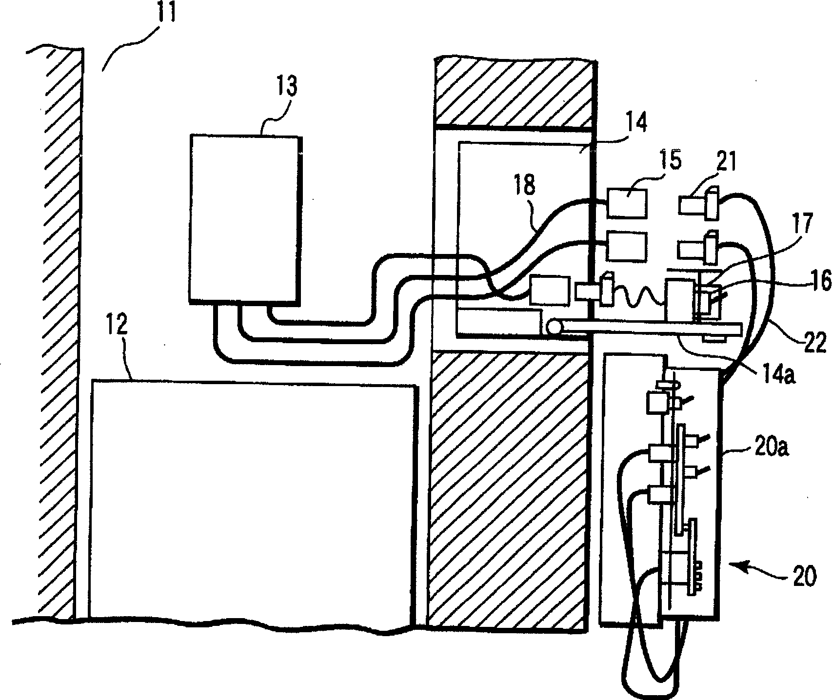
[0019] figure 1 It is a configuration diagram showing an elevator maintenance system according to a first embodiment of the present invention. In the figure, 11 denotes an elevator, 12 denotes a car, and 13 denotes a control panel of an elevator.
[0020] In the machine-room-less elevator, the control panel 13 is installed in the hoistway 11 . As the installation place of the control panel 13, it is preferable to place it in a place other than the pipe trench in the hoistway 11, and the position above the uppermost floor is preferable. This is because, when the control panel 13 is set in the pipe ditch in the liftway 11, when the pipe ditch partly enters water due to heavy rain for example, the control panel 13 may break down.
[0021] Here, in the first embodiment, the specific place in the building means here that the connector box 14 is installed in the elevator car on the uppermost floor. A connector 15 for connecting a maintenance tool 20 to be described later is accom...
no. 2 Embodiment
[0033] Next, a second embodiment of the present invention will be described.
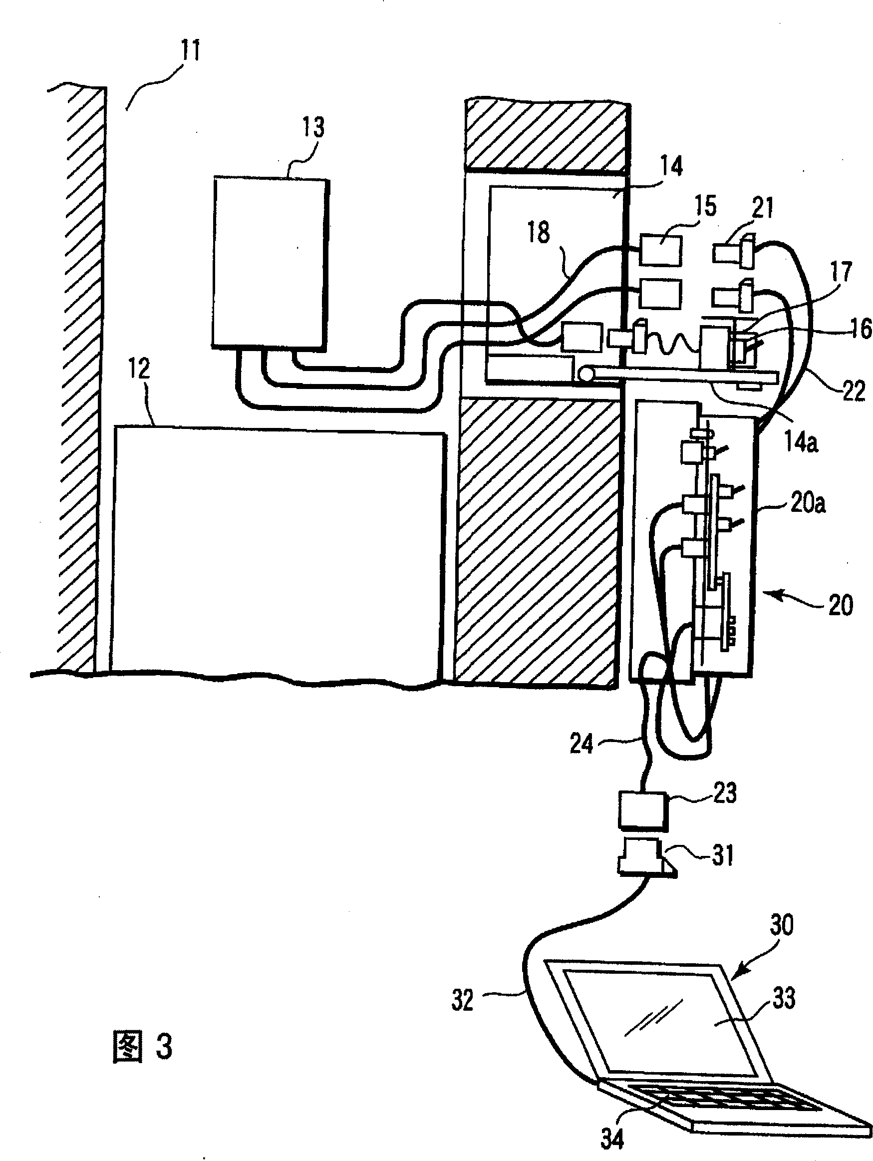
[0034] Fig. 3 is a structural diagram showing an elevator maintenance system according to a second embodiment of the present invention, showing a machine-room-less elevator in which a control panel 13 is provided in a hoistway 11 of a car 12 .
[0035] With the above-mentioned first embodiment ( figure 1 ) Similarly, the structure is that a connector box 14 is set in the uppermost elevator room, and maintenance work is performed by connecting the maintenance tool 20 to the connector 15 in the connector box 14.
[0036] Here, the second embodiment is characterized in that the maintenance tool 20 has an interface function for connecting to a computer 30 . That is, the connector 23 for computer connection is connected to the maintenance tool 20 via the cable 24 .
[0037] A port 31 detachably attached to the computer connection connector 23 is connected to a computer 30 via a cable 32 . In addition,...
no. 3 Embodiment
[0045] Next, a third embodiment of the present invention will be described.
[0046] Fig. 4 is a structural diagram showing an elevator maintenance system according to a third embodiment of the present invention, showing a machine-room-less elevator in which a control panel 13 is provided in a hoistway 11 of a car 12 .
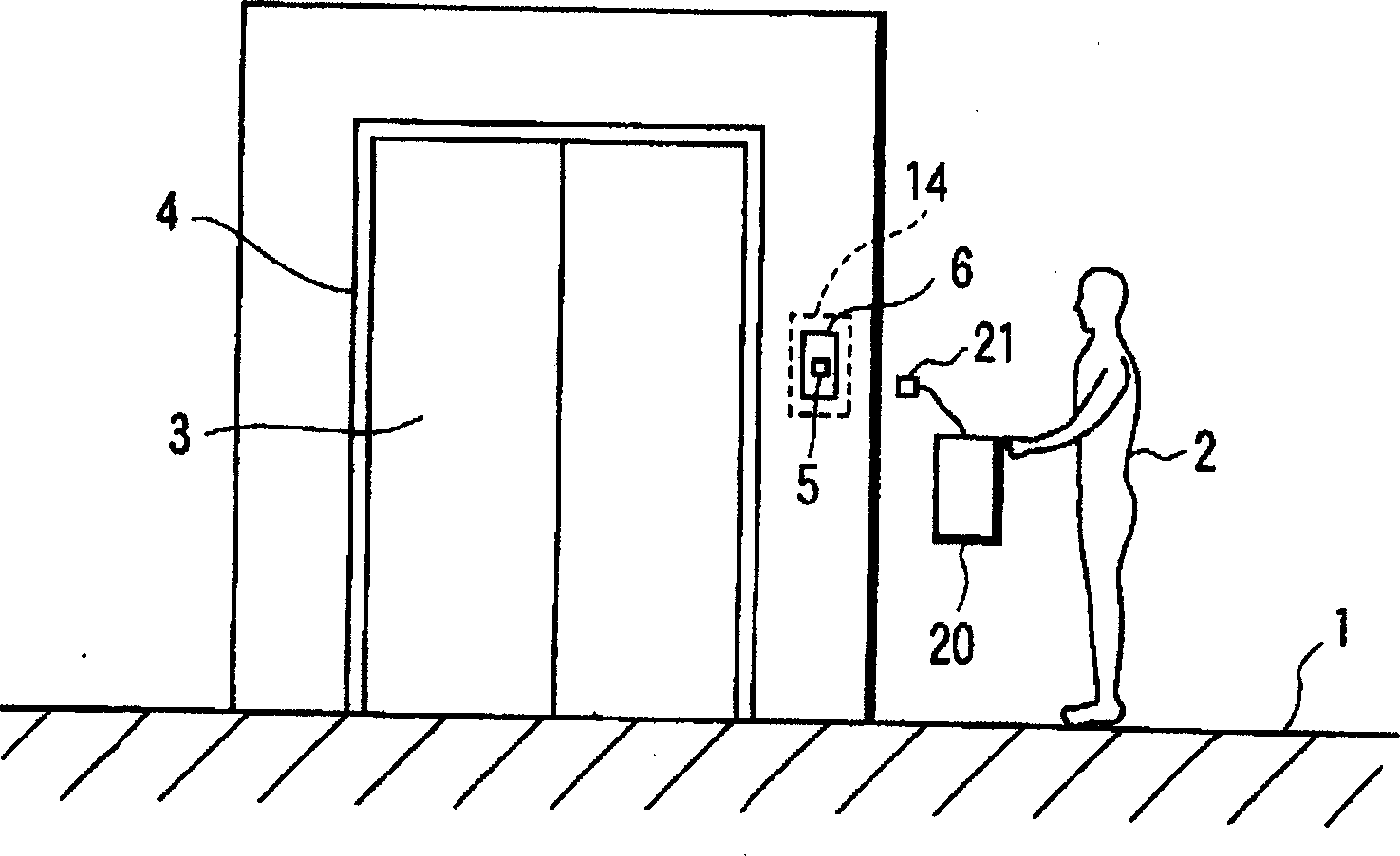
[0047] Similar to the above-mentioned first and second embodiments, the connector box 14 is installed at a specific place in the building, here, in the elevator car 1a on the uppermost floor. A connector 15 and the like for connecting the maintenance tool 20 are accommodated in the connector box 14 . In addition, although not particularly shown here, the connector 15 in the maintenance tool 20 is connected to the control panel 13 by a cable. In addition, the place where the connector box 14 is installed is inside the operation panel 6 of the hall button 5 in the elevator car 1a on the uppermost floor.
[0048] The third embodiment here is characterized in th...
PUM
 Abstract
Description
Claims
Application Information
 - R&D Engineer
- R&D Manager
- IP Professional
- Industry Leading Data Capabilities
- Powerful AI technology
- Patent DNA Extraction
Browse by: Latest US Patents, China's latest patents, Technical Efficacy Thesaurus, Application Domain, Technology Topic.
© 2024 PatSnap. All rights reserved.Legal|Privacy policy|Modern Slavery Act Transparency Statement|Sitemap