Switch power supply module

A technology of switching power supply and resistance, which is applied in the direction of electrical components, adjusting electric variables, magnetic field/electric field shielding, etc. It can solve the problems of easy radiation of power frequency, few suitable models, and influence on TV effect, etc., and achieves low cost, No radiation, good shielding effect

Inactive Publication Date: 2004-08-25
吴雪峰
View PDF0 Cites 2 Cited by
  • Summary
  • Abstract
  • Description
  • Claims
  • Application Information

AI Technical Summary

Problems solved by technology

There is a power supply board that can be equipped with a power supply part, but there are many disadvantages, such as large volume, many connectio

Method used


Image

  • Switch power supply module
  • Switch power supply module

Examples


Example Embodiment

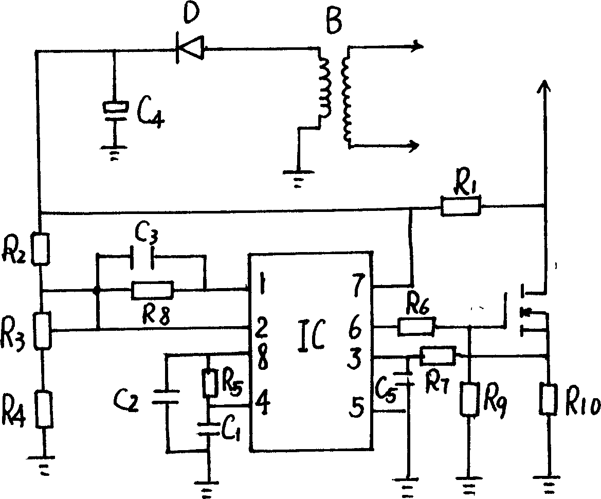
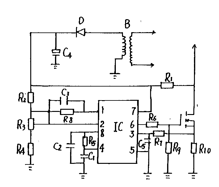
[0007] The present invention will be described in detail below with reference to the drawings.

[0008] The module of the present invention is integrally packaged in an aluminum shell, and is composed of an integrated circuit IC (SG3842), a field effect tube GZ, resistors R1-R10, transformer B, diode D, and capacitors C1-C4. The B secondary pole of the transformer is connected to the voltage divider resistors R2, R3, R4 in series after the diode D. One end of R2 is connected to IC pin 7, and R1 is connected to the drain of the field effect transistor GZ, and the other end is connected to the resistor R8 in parallel with the capacitor C3 After the branch is connected to IC pin 1, the center contact of the potentiometer is connected to the contact of the parallel branch of R2, resistor R8 and capacitor C3, and connected to IC pin 2, resistor R5 and C1 are connected in series and then connected to C2 in parallel, and It is connected across the IC pin of the integrated circuit and the...


PUM


Abstract

This invention discloses a switch power module packaged in an Al shell composed of an IC,a fieldistor, resistors, a transformer, a diode and capacitors with good radiation and shield, no radiation and good voltage regulation, simple structure and low cost.

Description

technical field [0001] The invention relates to a switching power supply module. Background technique [0002] The early switching power supply was not easy to repair if it was damaged. Because the power supply is broken, the TV does not work, and the corner voltage is abnormal, so it is difficult to repair. Because of its long-term work under high voltage, the power supply is a vulnerable product. There is an existing power supply board, which can be equipped with a power supply part, but there are many disadvantages, such as large volume, many connections, few suitable models, and because there are too many leads, the power frequency is prone to radiation, which affects itself and other TV effects. Contents of the invention [0003] The object of the present invention is to overcome the above-mentioned defects in the prior art and provide a switching power supply module with good heat dissipation, shielding effect and no radiation. [0004] The invention is realized t...

Claims


Application Information

Patent Timeline
IPC IPC(8): H02M1/00H02M3/155H05K7/20H05K9/00
Inventor 吴雪峰
Owner 吴雪峰
Why Eureka
Try Eureka