

Shielding device of camera and intelligent terminal
A technology of shielding device and intelligent terminal, applied in the field of cameras, can solve the problems of easy damage, influence of flexible circuit boards, poor shielding, etc., and achieve the effect of good support, good shielding effect, and not easy to damage.
- Summary
- Abstract
- Description
- Claims
- Application Information
AI Technical Summary
Problems solved by technology
Method used
Image

Examples
Embodiment 1
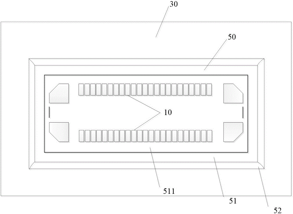
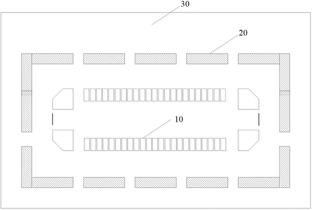
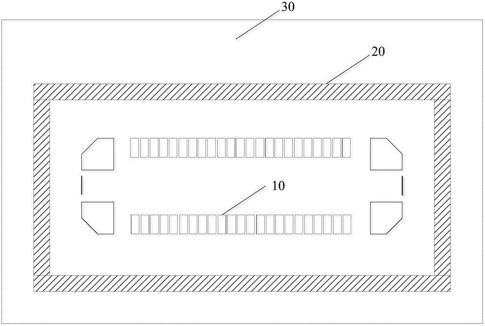
[0023] see Figure 1-Figure 4 The shielding device provided by Embodiment 1 of the present invention includes a first exposed copper area 20 disposed on the PCB 30 at the periphery of the camera connector 10 and a shielding frame 50 attached to the first exposed copper area 20 . Specifically, the shielding frame 50 is attached on the first exposed copper area 20 by welding.
[0024] Preferably, the first exposed copper region 20 is in the shape of scattered points and scattered blocks (see figure 2 ) or a continuous loop (see image 3 ) is surrounded by the periphery of the camera connector 10, and its function is mainly to weld the shielding frame 50. The shielding frame 50 is generally made of metal, preferably, the shielding frame 50 is made of 0.2mm stainless steel or nickel nickel. The structure of the shielding frame 50 is as Figure 4 As shown, it includes a top surface 51 , four side surfaces 52 and a camera connector placement hole 511 disposed on the top surface...
Embodiment 2
[0027] see Figure 5-Figure 7 , the shielding device provided in Embodiment 2 of the present invention includes a first exposed copper area 20 located on the periphery of the camera connector 10 on the PCB 30, a second exposed copper area 40 located on the periphery of the first exposed copper area 20, and a sticker The shielding frame 50 attached on the first exposed copper area 20 . Wherein, the shielding frame 50 includes a top surface 51 , four side surfaces 52 and a camera connector placement hole 511 provided on the top surface 51 .
[0028] Specifically, the first exposed copper area 20 is in the shape of scattered points and scattered blocks (see figure 2 ) or a continuous loop (see image 3 ) is surrounded by the periphery of the camera connector 10, and its function is mainly to weld the shielding frame 50. The second exposed copper area 40 is scattered dots or scattered blocks (see Figure 6 , Figure 7 ), which can further reduce the radiation of the camera. ...
Embodiment 3
[0031] see Figure 8-Figure 9 The shielding device provided by Embodiment 3 of the invention includes a first exposed copper area 20 located on the periphery of the camera connector 10 on the PCB 30, a second exposed copper area 40 located on the periphery of the first exposed copper area 20, and affixed to the The shielding frame 50 on the first exposed copper area 20 . Wherein, the shielding frame 50 includes a top surface 51 , four side surfaces 52 and a camera connector placement hole 511 provided on the top surface 51 . A protrusion 522 is provided on the outer wall of the side surface 52 of the shielding frame, and a notch 521 is provided at the connection between the side surface 52 and the first exposed copper area 20 . The shielding frame 50 is generally made of metal, and is attached to the first exposed copper area 20 by welding. Preferably, the shielding frame 50 is made of 0.2mm stainless steel or nickel nickel.
[0032] The shielding device provided by the emb...
PUM
| Property | Measurement | Unit |
|---|---|---|
| Thickness | aaaaa | aaaaa |
Abstract
Description
Claims
Application Information