Venting structure of pressure cooker and pressure cooker with the same

A pressure cooker and exhaust pipe technology, which is applied in the field of cooking and kitchen utensils, can solve problems such as failure, vertical rib bending, and affecting the service life of the pressure cooker, and achieve the effect of improving the service life, not being easy to bend, and increasing the service life

Pending Publication Date: 2017-10-27
GREE ELECTRIC APPLIANCES INC
View PDF8 Cites 65 Cited by
  • Summary
  • Abstract
  • Description
  • Claims
  • Application Information

AI Technical Summary

Problems solved by technology

Because the vertical rib is fixed, the matching part will still rotate within a small range to make the inclined surface cooperate with the vertical rib and drive the pressure limiting valve to move upward. The frictional force exerted by the rotation of the pressure valve on it will easily cause the vertical rib to bend and fail after long-term use, which will affect the service life of the pressure cooker

Method used


Image

  • Venting structure of pressure cooker and pressure cooker with the same
  • Venting structure of pressure cooker and pressure cooker with the same

Examples


Embodiment 1

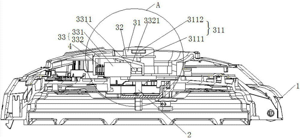
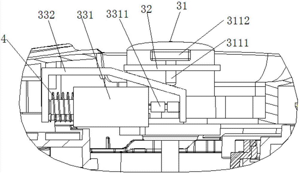
[0031] A kind of pressure cooker, it comprises pot body and the pot cover 1 that covers on described pot body, as figure 1 As shown, the pot cover 1 is provided with an exhaust pipe 2, and the exhaust pipe 2 is provided with an exhaust structure, figure 2 Shown is a schematic diagram of the exhaust structure described in this embodiment, which includes a pressure limiting valve 31, a limiter 32 and a drive assembly 33, the pressure limiting valve 31 is arranged on the exhaust pipe 2, and the pressure limiting valve 31 is The pushing part 311 is fixedly arranged; the limiting part 32 is fixed on the lid 1 of the pressure cooker; the driving assembly 33 drives the pushing part 311; the limiting part 32 restricts the pressure limiting valve 31 to only be able to The pipe axis moves up and down, and the driving assembly 33 drives the pushing member 311 to move up and down along the exhaust pipe axis.

[0032] In this embodiment, the pushing part 311 includes an extension part 31...

Embodiment 2

[0039] An electric pressure cooker, which includes a pot body and a pot cover 1 that is covered on the pot body, the pot cover 1 is provided with an exhaust pipe 2, and the exhaust pipe 2 is provided with an exhaust structure. The exhaust structure in the embodiment includes a pressure limiting valve 31, a limiting member 32 and a driving assembly 33, the pressure limiting valve 31 is arranged on the exhaust pipe 2, and a pushing member 311 is fixedly arranged on the pressure limiting valve 31; The positioning member 32 is fixed on the pot cover 1; the driving assembly 33 drives the pushing member 311; the limiting member 32 restricts the pressure limiting valve 31 to move up and down along the exhaust pipe axis, and the driving assembly 33 The pushing member 311 is driven to move up and down along the axis of the exhaust pipe.

[0040]In this embodiment, the pushing member 311 is a pushing plate extending outward from the side wall of the pressure limiting valve 31 . The lim...


PUM


Abstract

The invention relates to a cooking device, in particular to a venting structure of a pressure cooker and the pressure cooker with the same. The venting structure of the pressure cooker includes a pressure limiting valve, a limiting part and a driving component, wherein the pressure limiting valve is arranged on a venting pipe and fixedly provided with a pushing component; the limiting part is fixed to a cooker cover; the driving component drives the pushing component; the movement of the pressure limiting valve is limited to an axis of the venting pipe in a vertical direction by the limiting part, and the driving component drives the pushing component to move vertically along the axis of the venting pipe. The venting structure of the pressure cooker and the pressure cooker with the same aim at solving the technical problems that when the pressure limiting valve of the pressure cooker is switched on, a plurality of components need to cooperate with one another, and a stud is likely to be broken to influence the service life of the pressure cooker; therefore, the venting structure of the pressure cooker with a longer service life and the pressure cooker with the same are provided.

Description

technical field [0001] The invention relates to a cooking and kitchen utensil. Specifically, it relates to an exhaust structure of a pressure cooker and a pressure cooker thereof. Background technique [0002] Because of its good cooking effect, fast speed, energy saving and other advantages, the electric pressure cooker has entered thousands of households and has become one of the necessary living appliances in the kitchen. Good-looking appearance, simple structure, has gradually become the leading product in the market. [0003] However, electric pressure cookers have the problems of difficult lid closing and suction pots in a hot state. In order to solve the above technical problems, electric pressure cookers in the prior art solve the problems of suction pots and difficult lid closures in a hot state by reducing the pressure difference inside and outside the electric pressure cooker. [0004] Chinese patent document CN105476461A discloses an electric pressure cooker, w...

Claims


Application Information

Patent Timeline
Patent Type & Authority Applications(China)
IPC IPC(8): A47J27/08
CPCA47J27/0802
Inventor 柏长升张继东白建东车利超
Owner GREE ELECTRIC APPLIANCES INC
Why Eureka
Try Eureka