Vehicle mounted dynamic battery changing system

A battery box, battery box technology, applied in power units, electric power units, vehicle parts, etc., can solve the problems of easy movement of batteries left and right, difficult to place batteries, easy to damage batteries, etc., to achieve rapid replacement, simplified structure, accurate positioning

Inactive Publication Date: 2008-07-09
BEIJING DIANBA TECH CO LTD +1
View PDF1 Cites 63 Cited by
  • Summary
  • Abstract
  • Description
  • Claims
  • Application Information

AI Technical Summary

Problems solved by technology

[0004] However, the loading and unloading device of this system has the following problems: 1. The battery is easy to move left and right when disassembling and installing the battery, which brings great trouble to the loading and unloading, especially when the battery is placed in the charging station for charging or the battery is sent to the battery. When entering the car body, it is difficult for the battery to be placed in place smoothly; 2. The battery is loaded and unloaded through the fork-type battery pack dial-out / dial-in device. On the one hand, it is easy to damage the battery, and on the other hand, it is not easy to operate

Method used


Image

  • Vehicle mounted dynamic battery changing system
  • Vehicle mounted dynamic battery changing system
  • Vehicle mounted dynamic battery changing system

Examples


Embodiment Construction

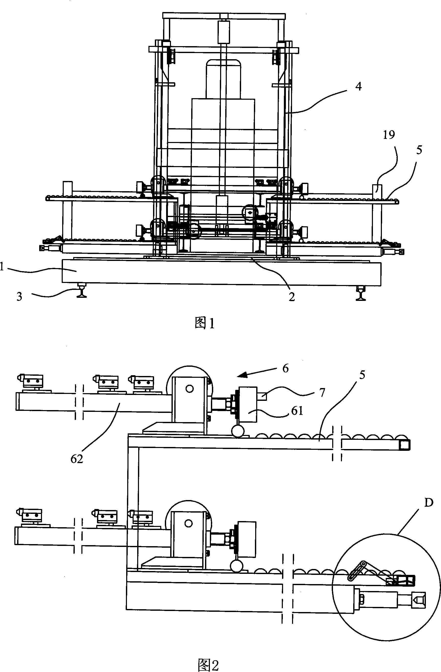
[0024] As shown in Figures 1, 2 and 4, the present invention includes: a parallel moving platform 1, a rotating platform 2, a track 3, a vertical lifting device 4 and a battery tray 5, the parallel moving platform 1 is located on the track 3, and can be moved along the track 3 Movement; the rotating platform 2 is set on the parallel moving platform 1, and the battery tray 5 is set on the rotating platform 2 through the vertical lifting device 4; the battery tray 5 is provided with an electromagnetic suction device 6 for sucking the battery box 14.

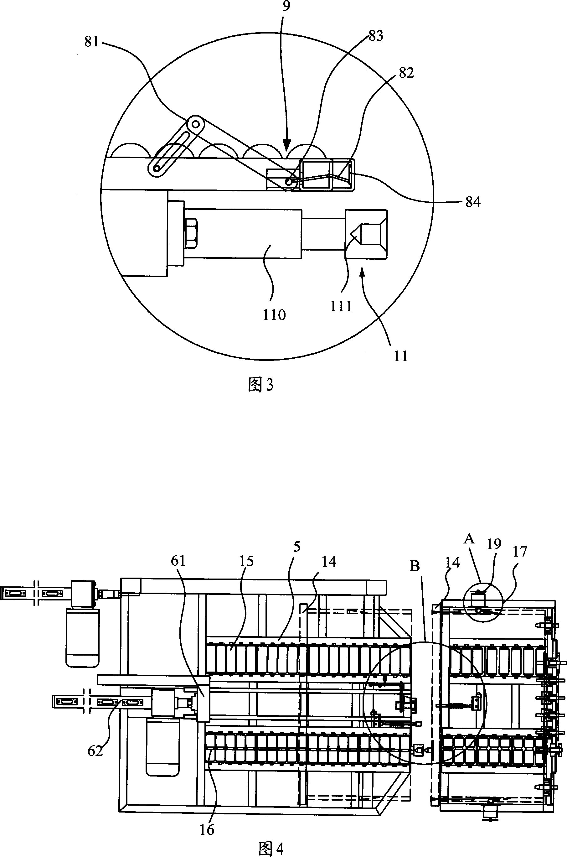
[0025] As shown in Figure 2, the electromagnetic suction device 6 includes: an electromagnetic chuck 61 and an electric cylinder 62. The electromagnetic chuck 61 moves back and forth on the battery tray 5 through the electric cylinder 62. When moving to the front end of the battery tray 5, the electromagnetic chuck 61 front end is set. When a travel switch 7 of the switch contacts the panel of the battery box 14, as shown in Figure ...


PUM


Abstract

The invention discloses a battery replacement system for power battery loaded on a vehicle. The system comprises a parallel mobile platform, a rotating platform, a track, a vertical lifting device and a battery tray. The parallel mobile platform is positioned on the track and moves along the track. The rotating platform is positioned on the parallel mobile platform. The battery tray is positioned on the rotating platform via the vertical lifting device. The battery tray is equipped with an electromagnetic suction device for drawing the battery box. The invention has the advantages of more convenient unloading of the battery box, more accurate positioning, and realizing the single loading and unloading of the battery box to be controlled within 3 minutes.

Description

technical field [0001] The invention relates to a replacement system for installing and removing a vehicle power battery. Background technique [0002] With the increase of oil prices and the seriousness of environmental pollution, as a substitute for fuel-based vehicles, people have developed natural gas vehicles, hydrogen fuel vehicles, solar vehicles and electric vehicles, among which electric vehicles are the most promising. . [0003] Patent 200410090796.0 "An Electric Bus System" discloses an electric vehicle powered by a vehicle-mounted power battery. The electric bus system includes: an electric bus equipped with a cassette battery pack, a charging station for charging the cassette battery pack, a cassette battery pack unloading device, etc.; Take it off and place it on the charging station for charging, and at the same time put the cassette battery pack that has been charged on the charging station on the electric bus. [0004] However, the loading and unloading ...

Claims


Application Information

Patent Timeline
Patent Type & Authority Applications(China)
IPC IPC(8): B60S5/06B65G47/46
Inventor 王震坡张建平
Owner BEIJING DIANBA TECH CO LTD
Why Eureka
Try Eureka