Nonwoven fabric

a nonwoven fabric and fiber technology, applied in the field of nonwoven fabrics, can solve the problems of entanglement of fibers to one another, inability to adjust the orientation or arrangement of fibers, and methods only manufacturing a simple sheet-like nonwoven fabric, so as to improve the resistance to damage during us

Active Publication Date: 2007-12-27
UNI CHARM CORP
View PDF38 Cites 65 Cited by
  • Summary
  • Abstract
  • Description
  • Claims
  • Application Information

AI Technical Summary

Benefits of technology

[0029]According to the present invention, such nonwoven fabric can be provided with open areas that improve resistance to damage during use.

Problems solved by technology

However, these methods have only entangled the fibers to one another and do not adjust the orientation or arrangement of the fibers in the fiber layer, the shape of the fiber layer or the like.
In other words, these methods only manufactured a simple sheet-like nonwoven fabric.
However, in the case of the nonwoven fabric disclosed in Patent Document 1, a fiber assembly constituting the nonwoven fabric is pressed between the projection part and the receiving supporting body to cause concavities and convexities and openings.
When the nonwoven fabric is used as a surface sheet in an absorbent article and the nonwoven fabric includes an arrangement of open areas among which small joining portions are provided, friction to the article in the width direction may cause fibers in the joining portion to easily unravel and result in damage to the article.

Method used


Image

  • Nonwoven fabric
  • Nonwoven fabric
  • Nonwoven fabric

Examples


embodiment 1

1. Embodiment 1

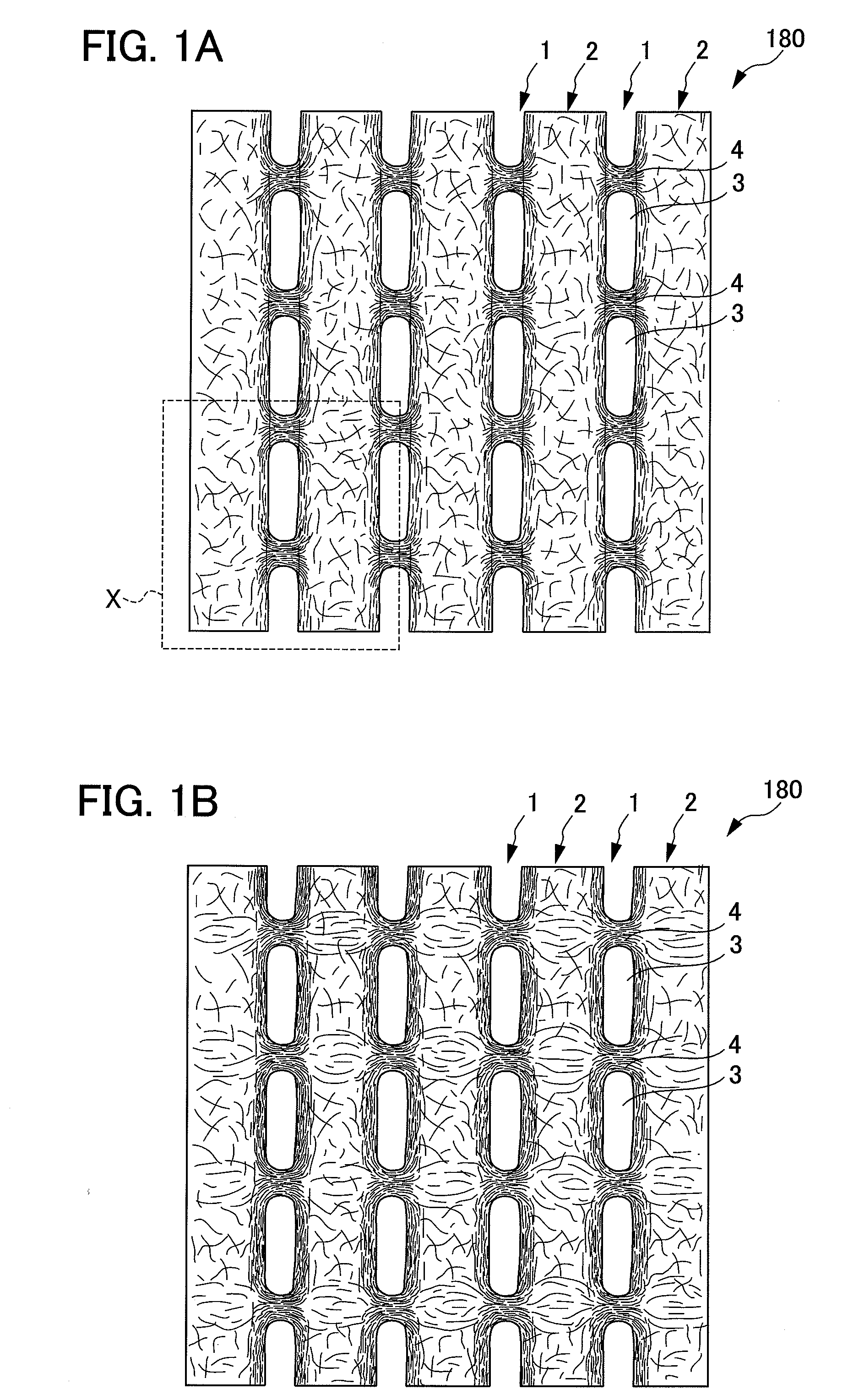
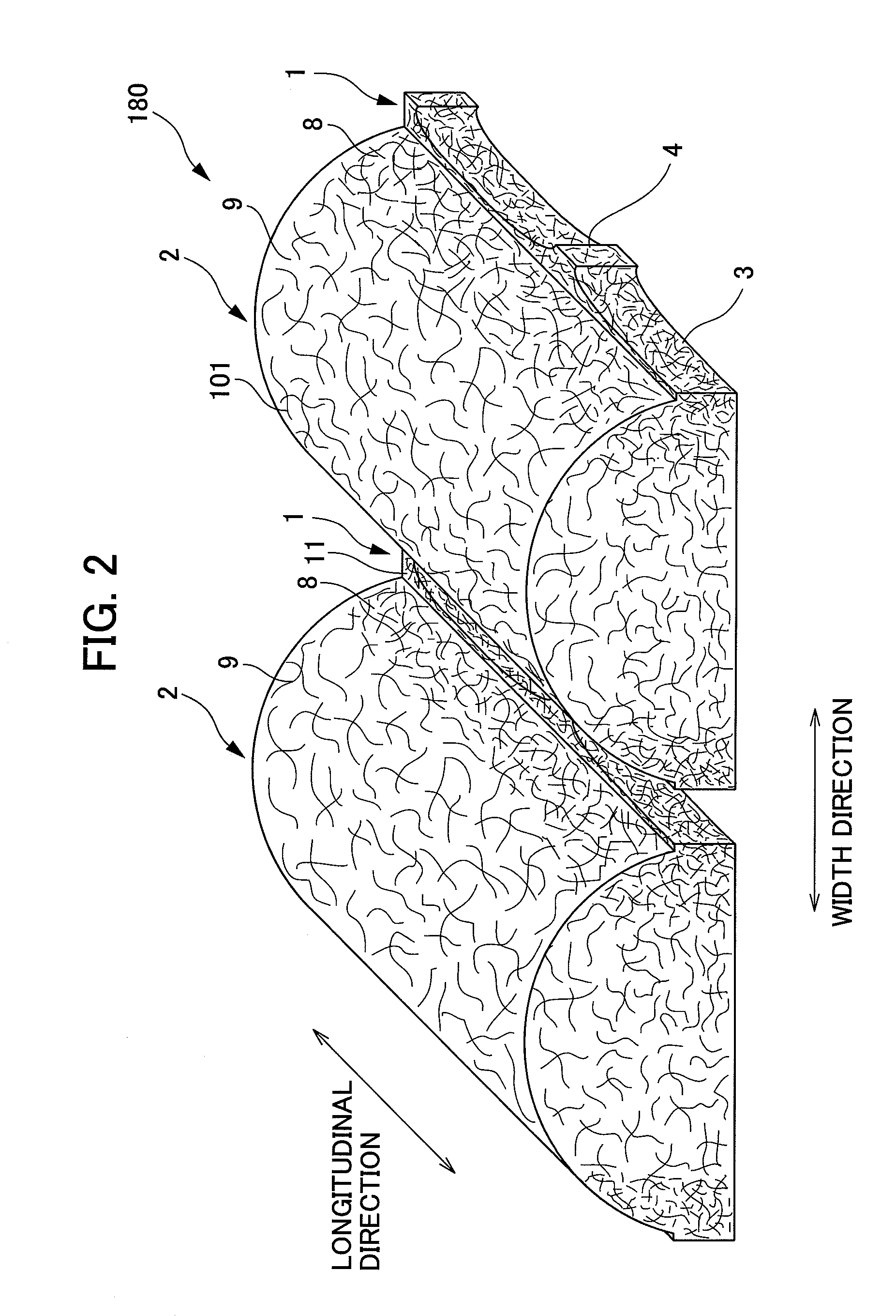
[0054]With reference to FIG. 1A, FIG. 1B, FIG. 2, and FIG. 4, the first embodiment of the nonwoven fabric of the present invention will be described.

1.1. Shape

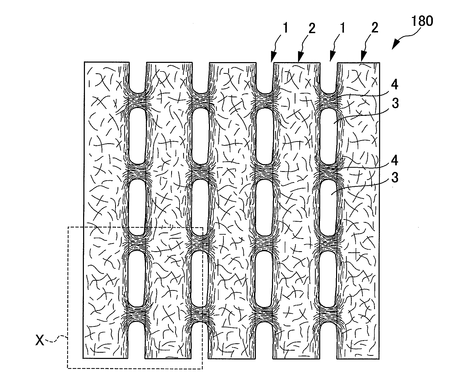
[0055]As shown in FIG. 1A, FIG. 1B, and FIG. 2, nonwoven fabric 180 of the first embodiment is structured so that a plurality of groove portions 1 are arranged at one surface of the nonwoven fabric 180 along the first direction (hereinafter referred to as longitudinal direction) with a substantially equal interval therebetween. In the groove portions 1 of the nonwoven fabric, open areas 3 and joining portions 4 are alternately arranged with a substantially equal interval. The respective plurality of open area 3 is formed to have a substantially circular or a substantially elliptical shape. In the first embodiment, the groove portions 1 are arranged in parallel to one another with a substantially equal interval. However, the invention is not limited to this. The respective adjacent groove portions 1 also may be a...

embodiment 2

2.1. Embodiment 2

[0160]With reference to FIG. 10, the second embodiment of the nonwoven fabric of the present invention will be described.

[0161]As shown in FIG. 10, nonwoven fabric 182 of this embodiment is different from the nonwoven fabric of the first embodiment in a surface of the nonwoven fabric 182 opposite to a face including the groove portion 1 and the convex portion 2. The following section will describe the difference between that of the first and second embodiments.

2.1.1. Nonwoven Fabric

[0162]The nonwoven fabric 182 of this embodiment is structured so that one surface includes the groove portions 1 and the convex portions 2 are alternately arranged so as to be in parallel to one another. The other surface side of nonwoven fabric 182 includes a region constituting a bottom face of the convex portion 2 formed to protrude in a direction along which the convex portion 2 protrudes. In other words, the nonwoven fabric 182 is structured so that the other surface of the nonwoven...

embodiment 3

2.2. Embodiment 3

[0166]With reference to FIG. 11 and FIG. 12, the third embodiment of the nonwoven fabric of the present invention will be described.

2.2.1. Nonwoven Fabric

[0167]As shown in FIG. 11, nonwoven fabric 184 of the third embodiment is different to the nonwoven fabric of the first embodiment in that the nonwoven fabric 184 protrudes in a wave-like manner. The following section will mainly describe the difference between that of the first and third embodiments.

[0168]The nonwoven fabric 184 of the third embodiment is structured so that the entire nonwoven fabric has an undulating surface substantially orthogonal to a direction along which the groove portion 1 and the convex portion 2 extend.

2.2.2. Manufacture Method

[0169]According to the third embodiment the manufacture of the nonwoven fabric 184 is by the same method as that of the first embodiment except for the shape of a supporting member, as an air permeable supporting member. Specifically, a supporting member 280 of the...


PUM

PropertyMeasurementUnit
lengthaaaaaaaaaa
densityaaaaaaaaaa
thicknessaaaaaaaaaa

Abstract

A nonwoven fabric that is not easily damaged during use is provided. A fiber web supported by a predetermined supporting member from the lower face side is blown with fluid, mainly composed of gas, from the upper face side of the fiber web to move fibers that constitute the fiber web, thereby forming at least a plurality of open areas. The nonwoven fabric includes a plurality of open areas continuously formed along a predetermined direction with a predetermined interval and a plurality of joining portions, each of which are formed between the open areas adjacent to each other in a predetermined direction.

Description

[0001]This application is based on and claims the benefit of priority from Japanese Patent Application No. 2006-174505, filed on Jun. 23, 2006, and Japanese Patent Application No. 2006-270110, filed on Sep. 29, 2006, the content of which are incorporated herein by reference.BACKGROUND OF THE INVENTION[0002]1. Field of the Invention[0003]The present invention relates to nonwoven fabric.[0004]2. Related Art[0005]Conventionally, nonwoven fabrics are used in a variety of fields, for example, sanitary products such as disposable diaper and sanitary napkin, cleaning products such as wipers and medical products such as masks. Such nonwoven fabrics are used in many different fields, but when actually used in products of each of those fields, it is necessary that the nonwoven fabric are manufactured with the properties and structures appropriate for their intended use.[0006]Nonwoven fabric is manufactured by, for example, using a dry method or a wet method to form a fiber layer (fiber web) a...

Claims


Application Information

Patent Timeline
Patent Type & Authority Applications(United States)
IPC IPC(8): B32B3/10A61F13/15A61F13/49A61F13/511D04H1/492D04H1/70D04H1/732D04H1/76
CPCA61F13/51Y10T428/2457A61F13/5146A61F13/536A61F13/53713A61F13/53717A61F2013/15016A61F2013/15365A61F2013/15422A61F2013/53778A61F2013/53782D04H1/465D04H13/005Y10T428/24603Y10T428/24942Y10T428/24124Y10T428/24273Y10T428/24612Y10T428/24331Y10T428/24322Y10T428/2495Y10T428/24992Y10T428/24595A61F13/512D04H1/495Y10T442/60Y10T442/643Y10T442/696D04H1/76D04H3/07
Inventor NODA, YUKIISHIKAWA, HIDEYUKIMIZUTANI, SATOSHITANI, KOICHIROKIMURA, AKIHIRO
Owner UNI CHARM CORP
Why Eureka
Try Eureka