High-speed mezzanine connector

A technology of central connectors and connectors, which is applied in the direction of connections, components of connecting devices, contact parts, etc., can solve the problem of increasing the overall size of the connector structure, increasing the size of the connector, and failing to reduce the size of the connector, etc. question

Inactive Publication Date: 2004-09-15
MOLEX INC
View PDF0 Cites 36 Cited by
  • Summary
  • Abstract
  • Description
  • Claims
  • Application Information

AI Technical Summary

Problems solved by technology

Using an outer shield may also increase the size of the connection, defeating the purpose of reducing the size of the connection
Using an outer shield also requires the two shells to overlap, thus increasing the overall size of the connector structure

Method used


Image

  • High-speed mezzanine connector
  • High-speed mezzanine connector
  • High-speed mezzanine connector

Examples


Embodiment Construction

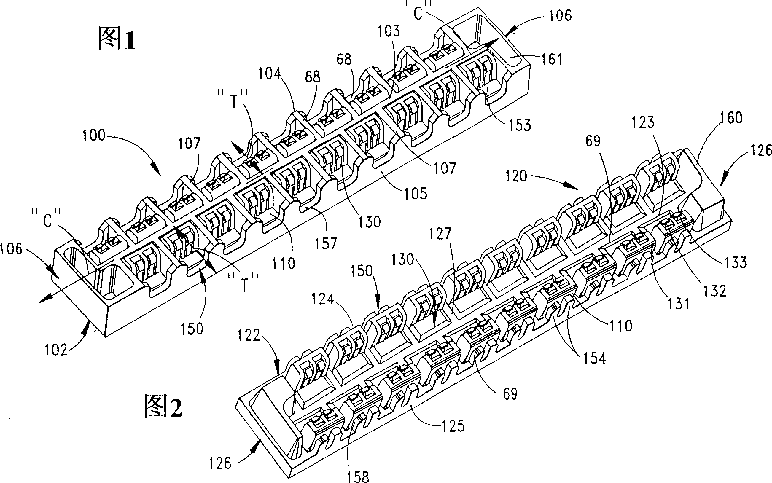
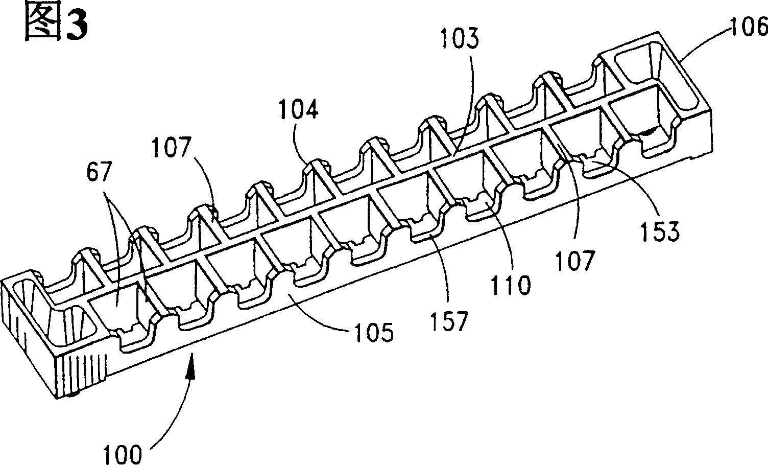
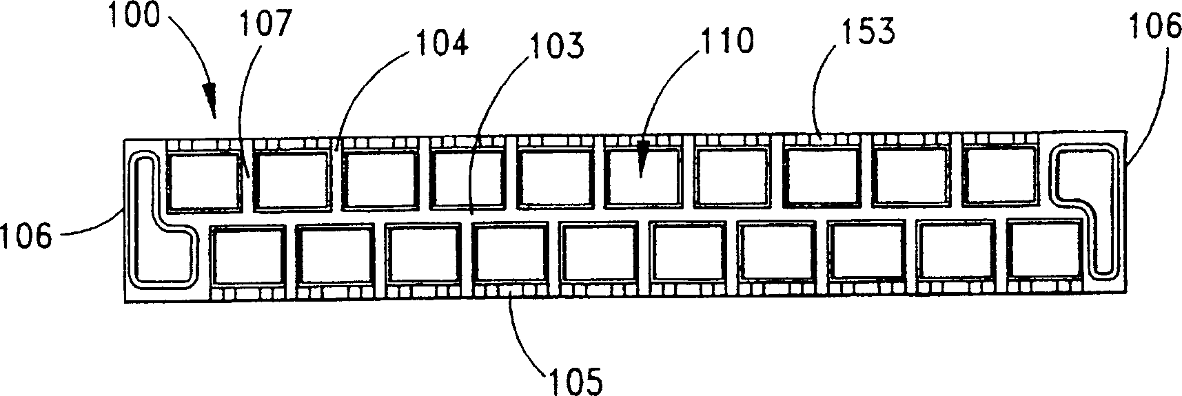
[0068] Figure 1 shows a receptacle connector assembly 100 and Figure 2 shows a plug connector assembly 120, both constructed in accordance with the principles of the present invention. Each assembly includes an insulating housing 102 , 122 . Each housing has a respective central wall 103, 123 extending substantially the entire length of the connector housing, and a pair of side walls 104, 105 and 124, 125. These walls terminate at the ends 106, 126 of the connector assembly. A plurality of spacer walls 107, 127 extend laterally from the central wall 103, 123 to the side walls and, together with the central and side walls of the connector assembly, form a plurality of cavities or openings 110 distributed longitudinally along the connector housing. As shown in Figures 1-5, these cavities 110 are staggered relative to each other on both sides of the longitudinal centerline C of the connector assembly, that is, the transverse centerline T of the cavity on one side of the center w...


PUM


Abstract

A board to board connector for use in high speed signal transmission applications includes male and female connector components that interengage with each other. Each of the male and female parts has an insulative housing that holds a plurality of individual terminal assemblies in cavities defined by corresponding walls of each connector component. The exterior surfaces of the connector components are plated with a metal so as to provide a unitary grounding datum around each of the individual terminal assemblies. Each of the connector components may utilize a center engagement member that runs lengthwise through the connector components, one of the center engagement members having a contact blade formed integrally therewith and the other of the center engagement members including a plurality of spring arms, also integrally formed with the connector component so that the grounding shield portions of the two connectors make contact with each other first before the terminals of the connector make contact.

Description

technical field [0001] The present invention relates generally to high speed connectors, and more particularly to high speed intermediate or board-to-board connectors. Background technique [0002] The electronics industry has been improving the speed and efficiency of its devices not only in size but also in speed of operation. Also, there is now greater emphasis on reducing component costs in the electronics industry, including the cost of connectors. To facilitate the manufacture of these devices, connections that operate at high speeds are required. Typical configurations for high-speed connectors include the use of separate metal shields that can be installed along one or both sides of the connector. Signal terminals are typically mounted inside the connector housing and spaced apart from the shield. This construction involves forming and installing a separate shield, which increases the cost of the connection. Using an outer shield may also increase the size of the...

Claims


Application Information

Patent Timeline
Patent Type & Authority Applications(China)
IPC IPC(8): H01R12/00H01R12/50H01R13/28H01R13/658
CPCH01R13/65807H01R23/688H01R13/28H01R13/65805Y10S439/931H01R13/6599H01R12/7082
Inventor 维克托·萨德尔肯尼斯·M·斯泰尔斯肯特·E·雷尼尔
Owner MOLEX INC
Why Eureka
Try Eureka