
Board-to-board connector having sloped guide surfaces with a common edge

a technology of guide surface and connector, which is applied in the direction of incorrect coupling prevention, coupling device connection, printed circuit structure association, etc., can solve the problems of increasing the difficulty and time of fitting operation, and achieves the effect of avoiding fumbling operation for fitting, completing fitting operation in a rather short period of time, and preventing damage to the first and second terminals

Inactive Publication Date: 2013-03-19
MOLEX INC
View PDF12 Cites 22 Cited by
  • Summary
  • Abstract
  • Description
  • Claims
  • Application Information

AI Technical Summary

Benefits of technology

The present invention provides a board-to-board connector that prevents damage to terminals during fitting. The connectors have a configuration where the terminals are spaced apart from each other, even when the fitting faces are brought to slide on top of each other during fitting. This prevents damage to the terminals and allows for easy fitting in a short period of time, with high reliability and operability.

Problems solved by technology

For this reason, when the fitting face of first housing 811 is made to slide on the fitting face of second housing 911, first and second terminals 861, 961 are brought into abutting contact, and may rub against each other, potentially causing damage.
This increases both the difficulty and time to perform the fitting operation.

Method used


Image

  • Board-to-board connector having sloped guide surfaces with a common edge
  • Board-to-board connector having sloped guide surfaces with a common edge
  • Board-to-board connector having sloped guide surfaces with a common edge

Examples


Embodiment Construction

[0029]While the Present Disclosure may be susceptible to embodiment in different forms, there is shown in the figures, and will be described herein in detail, specific embodiments, with the understanding that the disclosure is to be considered an exemplification of the principles of the present disclosure, and is not intended to limit the present disclosure to that as illustrated. In the embodiments illustrated herein, representations of directions such as up, down, left, right, front, rear and the like, used for explaining the structure and movement of the various elements of the present disclosure, are not absolute, but relative. If the description of the position of the elements changes, it is assumed that these representations are to be changed accordingly.

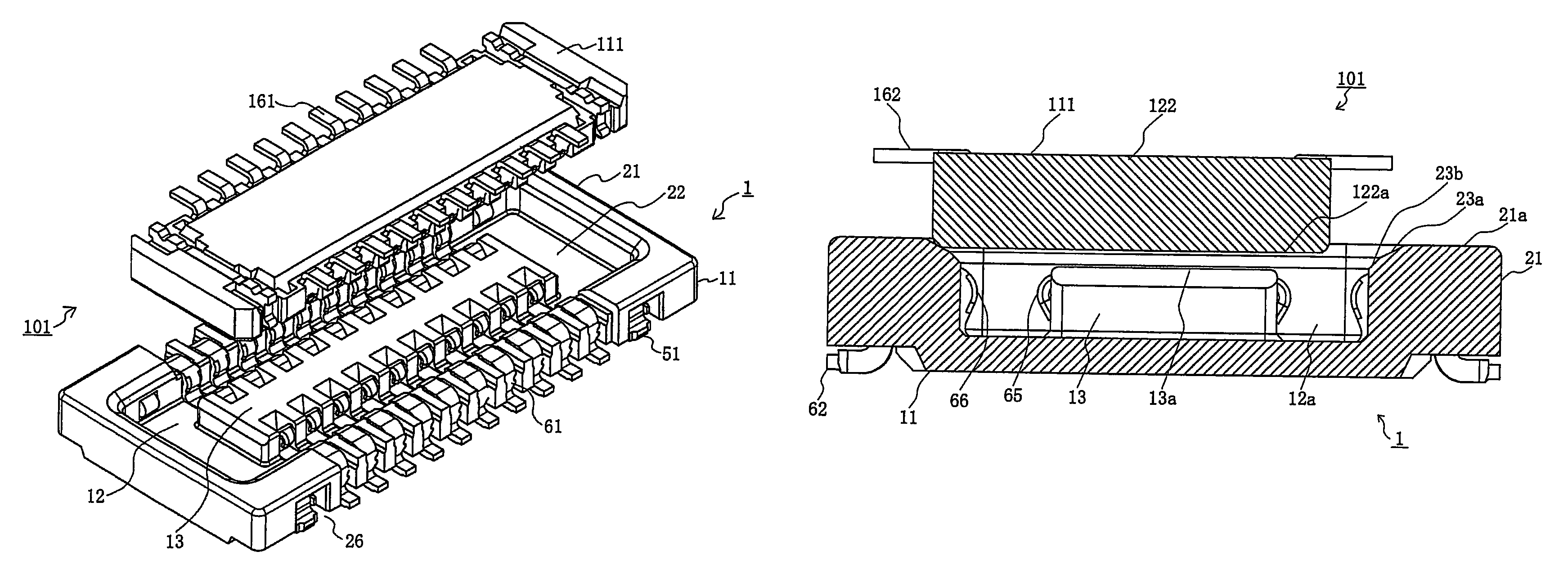
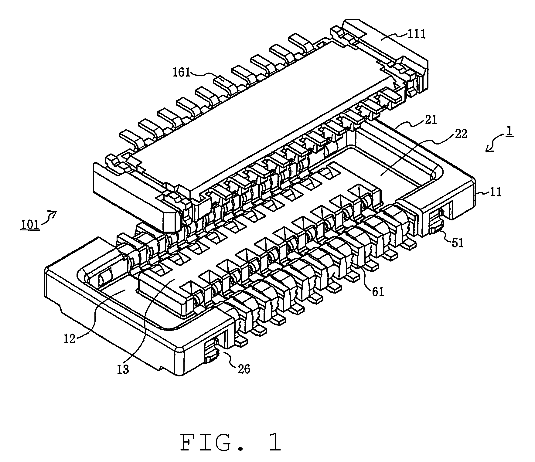
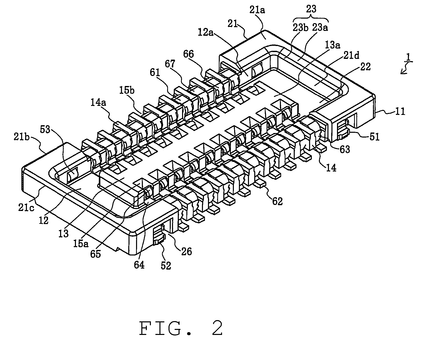
[0030]FIG. 1 is a perspective view of a first and a second connectors of a board-to-board connector according to an embodiment of the Present Disclosure, as viewed from a fitting face of the first connector, illustrating a sta...


PUM


Abstract

A board-to-board connector comprising a first connector and a second connector is disclosed. The first connector has a first housing mounted on first terminals. The second connector is configured to be engaged, by fitting, with the first connector. The second connector has a second housing mounted on second terminals, which are configured to make contact with the first terminals. At least a part of an entrance end portion a concave guide portion is provided with a sloped guide surface formed therein. Due to the insertion of a second fitting guide portion into a concave guide portion, in such a manner that portions of the second fitting guide portion are brought into abutting contact with the sloped guide surface, the first and second terminals are spaced apart from each other in a state where fitting faces of the first and second housings are even with each other.

Description

BACKGROUND OF THE DISCLOSURE[0001]1. Field of the Disclosure[0002]The Present Disclosure relates, generally, to a board-to-board connector, and, more particularly, to a board-to-board connector having such a configuration that when a fitting face of a first housing of a first connector is even with a fitting face of a second housing of a second connector, first terminals of the first connector are spaced apart from second terminals of the second connector, so that when the fitting face of the first housing is brought to slide on the fitting face of the second housing during the fitting operation, the first terminals do not make abutting contact with the second terminals, thereby preventing damage.[0003]2. Description of the Related Art[0004]Board-to-board connectors are typically used to couple pairs of parallel circuit boards with each other. Such connectors are attached, by fitting, to respective opposing surfaces of the circuit boards so that the boards are electrically connected...

Claims


Application Information

Patent Timeline
Patent Type & Authority Patents(United States)
IPC IPC(8): H01R13/64
CPCH01R12/716H01R13/631H01R12/73H01R12/71H05K1/14
Inventor SUZUKI, HIROKAZUTAKEUCHI, RYOTARO
Owner MOLEX INC
Learn More