
Method and device for measuring specific component concentration

A specific component and measurement device technology, which is applied in the direction of measurement device, scattering characteristic measurement, color/spectral characteristic measurement, etc., can solve the problems affecting wavenumber signal information and measurement accuracy, etc.

Inactive Publication Date: 2004-10-13
PANASONIC CORP
View PDF2 Cites 10 Cited by
  • Summary
  • Abstract
  • Description
  • Claims
  • Application Information

AI Technical Summary

Problems solved by technology

[0006] In this way, by measuring the return light from the living body, although the concentration information of various components of the body fluid can be obtained, there is a problem that the liquid on the boundary between the optical element and the living body affects the measurement accuracy
[0015] That is, there is a problem that the state change of the boundary part between the living body and the optical element affects the information of the wavenumber signal in the existing measuring method. The purpose of the present invention is to solve the above problems, and to provide a method to solve the above problems even if there is a gap between the optical element and the living body. Method and device capable of stably and conveniently measuring concentration information of specific components contained in living body in the presence of liquids such as water, saliva or sweat, or when measuring multiple parts of living body

Method used


Image

  • Method and device for measuring specific component concentration
  • Method and device for measuring specific component concentration
  • Method and device for measuring specific component concentration

Examples


Embodiment 1

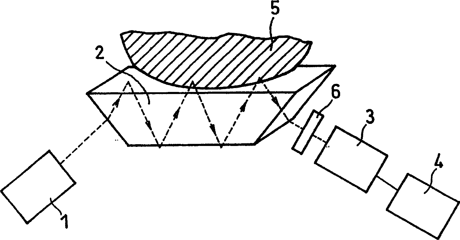
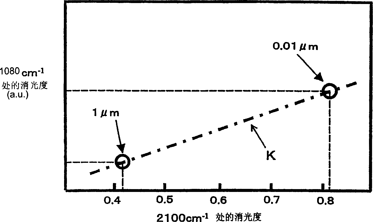
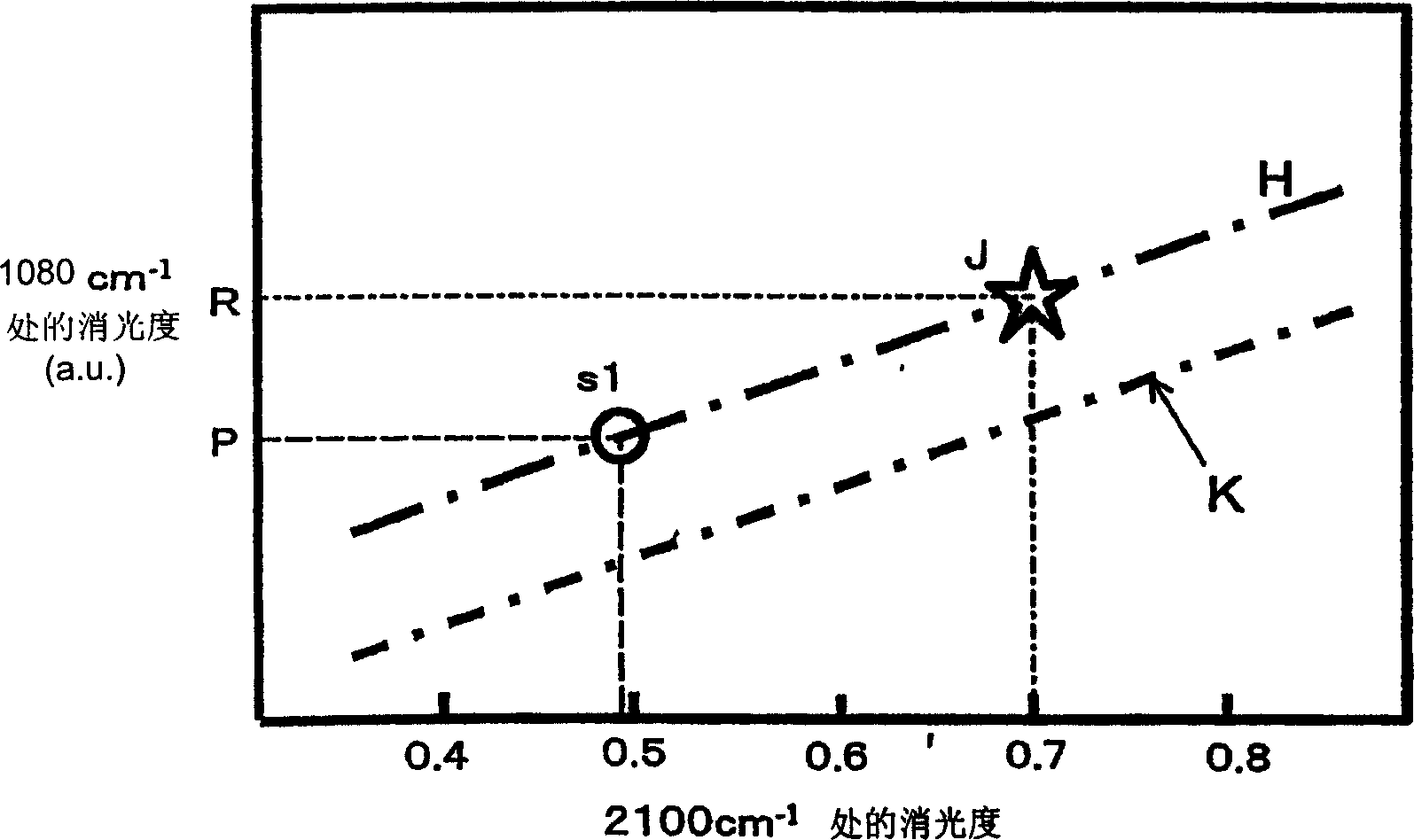
[0146] In this embodiment 1, using figure 1 The measuring device shown measures the glucose concentration using the measuring method of the present invention. in addition, image 3 It is a schematic diagram for explaining the method for correcting the wave number signal of glucose.

[0147] This measurement is performed on lips as the living body 5 . In addition, the wavenumber used when drawing the standard curve K is set to 2100cm -1 and 1080cm -1 .

[0148] In the measurement device used in this embodiment, a SiC light source is used as the light source 1 , and a germanium ATR element is used as the optical element 2 . In addition, a pyroelectric sensor is used as the photodetection element 3 and a computer is used as the signal processing device 4 . Although not shown in the figure, a spectroscopic device is provided between the light source 1 and the ATR element 2 .

[0149] Spectra were then measured as described below. First, the lips of the living body 5 are br...

Embodiment 2

[0161] In this example, the figure 1 The measuring device shown measures the concentration of glucose according to the measuring method of the present invention.

[0162] Figure 4 It represents the first and second two wave spectra obtained by keeping the ATR element 2 continuously attached to the living body 5 , ie, the lips, and performing two measurements. In the state where the living body 5 and the ATR element 2 are in close contact, the thickness of the saliva layer gradually changes, and the amount of light reaching the living body 5 changes. Therefore, the signal information of the first time and the second time are changed, and two kinds of spectrums are obtained.

[0163] Next, if Figure 5 As shown, assume that the 2100cm of the first spectrum is used -1 and 1080cm -1 The point represented by the extinction degree a1, b1 at the place is point C1, and the 2100cm of the second wave spectrum is used -1 and 1080cm -1 The point represented by the extinction degre...


PUM

PropertyMeasurementUnit
thicknessaaaaaaaaaa
thicknessaaaaaaaaaa

Abstract

The present invention provides easy and stable measurement of the concentration of a specific component contained in a living body, even when a fluid such as water, saliva or sweat is present between an optical element and the living body or when the measurement is taken at a plurality of measuring parts of a living body. In the measurement of the present invention, a calibration line to be used to correct the influence of a change of a fluid layer present between a living body and an optical element is determined, a measured value is corrected based on the calibration line and the concentration is obtained from the corrected value.

Description

technical field [0001] The present invention relates to a method and an apparatus for optically measuring the concentration of specific components such as blood sugar level, moisture, or cholesterol in a living body by measuring returned light from a living body. Background technique [0002] Conventionally, various methods of measuring specific components of a sample, especially a living body, using an optical measuring device have been proposed. For example, it is proposed to use a transparent attenuated total reflection (ATR) element with a pair of reflective surfaces parallel to each other as an optical element, and to make the optical element stick to the upper and lower lips to measure the blood sugar level (Japanese Patent Laid-Open Publication No. 9-113439 and Japanese Patent Laid-Open Publication No. 11-178799). [0003] Specifically, according to this method, an ATR element made of zinc selenide, silicon, or germanium is held between the mouth and the lips, and li...

Claims


Application Information

Patent Timeline
Patent Type & Authority Applications(China)
IPC IPC(8): G01N21/27A61B5/00G01N21/35G01N21/55
CPCA61B5/14546A61B5/1455A61B5/14532G01N21/552A61B5/4872G01N21/359A61B5/1495A47J27/002Y10S220/912
Inventor 大岛希代子内田真司盐井正彦
Owner PANASONIC CORP
Learn More